Film drawing device

A film device and film sandwich technology, applied in the directions of transportation and packaging, winding strips, sending objects, etc., can solve the problems of continuous film cutting, poor experience, and film jamming, so as to improve production efficiency and improve user experience. Excellent, fast and safe operation

Pending Publication Date: 2020-12-25
广东耐锢科技有限公司
View PDF0 Cites 4 Cited by
  • Summary
  • Abstract
  • Description
  • Claims
  • Application Information

AI Technical Summary

Problems solved by technology

[0003] However, there are still many problems in use: 1. It is difficult to change the film, and the position of the film is relatively high, which requires a hanger; it is dangerous to operate; 2. Different materials of the film will cause the film to be unsmooth or stuck. 3. The clamping film is not firm, resulting in continuous cutting when cutting the film. The occurrence of the above situation greatly affects the overall production efficiency, and the user experience is not good when using it.

Method used


Image

  • Film drawing device
  • Film drawing device

Examples


Embodiment Construction

[0018] A film pulling device of the present invention is described with reference to the accompanying drawings.

[0019] Such as Figure 1-Figure 2 Shown, as a kind of preferred embodiment of the present invention:

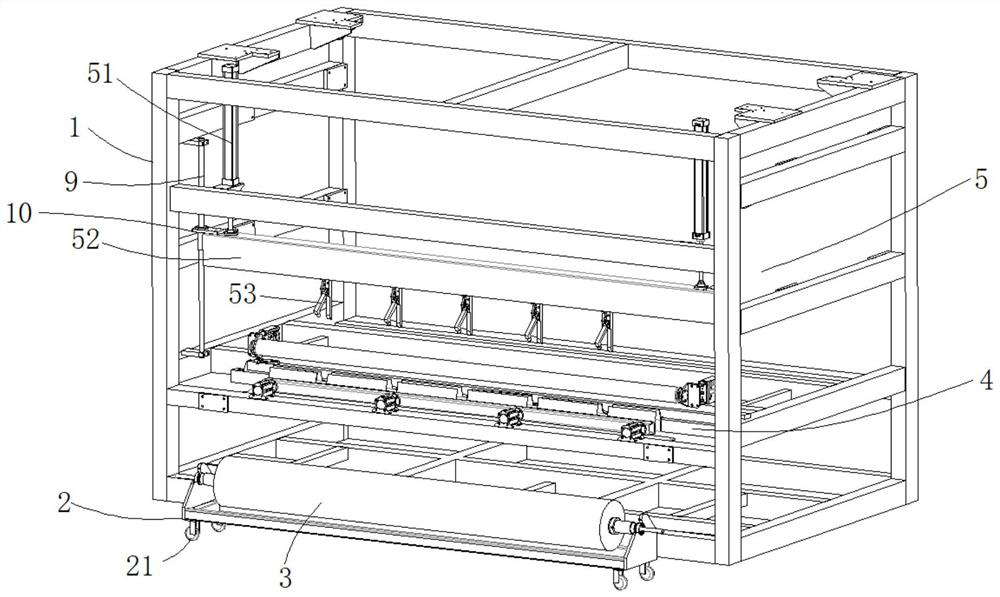
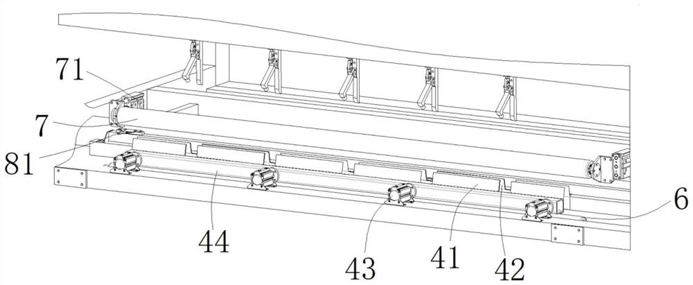
[0020] A film pulling device, comprising: a frame 1; a film frame 2, the film frame 2 is arranged on one side of the frame 1 and is arranged close to the bottom of the frame 1, on the film frame 2 The film release shaft 3 is installed, and the film release shaft 3 is used to place the film; the film clamping mechanism 4, the film clamping mechanism 4 is located above the film frame 2, and the film clamping mechanism 4 includes a first Clamping plate 41 and the second clamping plate 42, the first clamping plate 41 is movably installed on the frame 1, and a clamping film is formed between the first clamping plate 41 and the second clamping plate 42 Passage; Stretching mechanism 5, described stretching mechanism 5 is located at the top of described clamping mechani...


PUM


Abstract

The invention discloses a film drawing device. The film drawing device comprises a rack, a thin film frame, a film clamping mechanism, a stretching mechanism, a first transition shaft and a second transition shaft, wherein the thin film frame is arranged on one side of the rack and is close to the bottom of the rack, and a film placing shaft is arranged on the thin film frame and used for placinga thin film; the film clamping mechanism is arranged above the thin film frame and comprises a first film clamping plate and a second film clamping plate which are oppositely arranged; the first filmclamping plate is movably arranged on the rack, and a film clamping channel is formed between the first film clamping plate and the second film clamping plate; the stretching mechanism is arranged above the film clamping mechanism and comprises a stretching air cylinder, a cross beam and a plurality of film drawing clamps arranged on the cross beam, and the stretching air cylinder is in transmission connection with the cross beam; and the second transition shaft is arranged above the first transition shaft. In this way, at least one existing problem in the background art is effectively solved,and the overall production efficiency can be improved.

Description

technical field [0001] The invention relates to the technical field of film pulling equipment, in particular to a film pulling device. Background technique [0002] With the advancement of modern industrial technology, the use of films is becoming more and more extensive. Among them, the appearance of film pulling devices greatly facilitates the use of films by users. [0003] However, there are still many problems in use: 1. It is difficult to change the film, and the position of the film is relatively high, which requires a hanger; it is dangerous to operate; 2. Different materials of the film will cause the film to be unsmooth or stuck. 3. The clamping film is not firm, resulting in continuous cutting when cutting the film. The occurrence of the above situation greatly affects the overall production efficiency, and the user experience is not good when using it. [0004] Therefore, a solution is urgently needed. Contents of the invention [0005] The purpose of the pre...

Claims


Application Information

Patent Timeline
Patent Type & Authority Applications(China)
IPC IPC(8): B65H23/26B65H35/06
CPCB65H23/26B65H35/06
Inventor 刘玉娟杨月平
Owner 广东耐锢科技有限公司
Why Eureka
Try Eureka