
Setting and unsealing mechanism for underground sealing short section

A sub-joint and unsealing technology, which is applied in the directions of sealing/isolation, wellbore/well components, earthwork drilling and production, etc., can solve the problems of large unsealing force and difficult reset of the hydraulically driven sealing sub-joint, and achieves simple action, Easy to operate and low unsealing force

Active Publication Date: 2020-12-25
XIJING UNIV
View PDF18 Cites 2 Cited by
  • Summary
  • Abstract
  • Description
  • Claims
  • Application Information

AI Technical Summary

Problems solved by technology

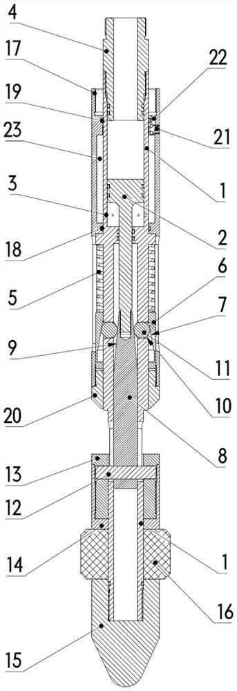
[0004] In order to overcome the above-mentioned problems in the prior art, the purpose of the present invention is to provide a setting and unsealing mechanism that can be used for downhole sealing pup joints, which can solve the problem of hydraulic drive The sealing nipple has the advantages of large unsealing force and difficult reset, and has the advantages of reasonable structure, convenient operation, reliable setting and sealing, high efficiency and practicality

Method used


Image

  • Setting and unsealing mechanism for underground sealing short section
  • Setting and unsealing mechanism for underground sealing short section

Examples


Embodiment Construction

[0016] The invention will be described in detail below in conjunction with the accompanying drawings.

[0017] see figure 1 , figure 2 , a setting and unsealing mechanism that can be used for downhole sealing pup joints, including a piston barrel 1, the upper end of the piston barrel 1 is threadedly connected to the upper joint 4, and the piston end of the piston rod 2 is arranged in the piston barrel 1 and below the upper joint 4 , the connecting end of the piston rod 2 is threadedly connected with the top of the push rod 8, the outer circumference of the top of the push rod 8 is provided with a first small-angle conical surface 9, the wall of the piston cylinder 1 is provided with a pressure guide hole 3, and the piston rod 2 piston end The lower space communicates with the external environment; the outer side of the piston cylinder 1 is sequentially covered with a sleeve 17, a spring 5, an inner cone sleeve 6, a spiral ring 20, a thrust ring 13, a pressure sleeve 14, a ru...


PUM


Abstract

The invention provides a setting and unsealing mechanism for an underground sealing short section. The setting and unsealing mechanism comprises a piston cylinder, wherein a piston rod is arranged inthe piston cylinder; the bottom of the piston rod is connected with the top end of a push rod; a sleeve, a spring, an inner taper sleeve, a screw ring, a thrust ring, a pressing sleeve, a rubber cylinder and a guide cone are sequentially sleeved on the outer side of the piston cylinder from top to bottom; an air cavity is formed between the piston cylinder and the sleeve; a plurality of circular holes are formed in the wall of the piston cylinder; steel balls are arranged in the circular holes; the inner sides of the steel balls are pressed on the push rod; the outer sides of the steel balls are clung to the inner taper sleeve; the upper end of the thrust ring is integrally connected with the lower end of the push rod through a bolt; the pressing sleeve is arranged on the outer side of thethrust ring; the rubber cylinder is arranged between the pressing sleeve and the guide cone at the bottom of the piston cylinder; the rubber cylinder communicates with the outside through a pressureguide hole; and the upper part of the rubber cylinder communicates with the outside through a pressure relief valve and a pressure relief hole; the inner taper sleeve, the push rod and the steel ballsform a double-conical-surface self-locking structure, so that the locking is more reliable, the borne reverse thrust is larger, and the locking cannot be invalid unless a part is damaged. The settingand unsealing mechanism has the advantages of reasonable structure, convenience in operation, safety and reliability in setting, high efficiency and practicability.

Description

technical field [0001] The invention belongs to the technical field of oil and gas field development, in particular to a setting and unsealing mechanism that can be used for downhole sealing pup joints. Background technique [0002] Downhole sealing nipples are often used in processes such as layered water injection, recovery pressure testing, seal inspection, and profile control. Blockage, separate the tubing string to facilitate subsequent testing or construction. [0003] The traditional sealing section is mainly driven by gravity impact, motor or hydraulic pressure; the gravity impact and motor driving force are small, and it is only suitable for self-sealing expansion rubber cartridges, which withstand small pressure differences and can only withstand one-way sealing; in addition, gravity impact There is no position locking mechanism, and the rubber cartridge has the risk of retreating; while the motor drive relies on the self-locking of the lead screw to prevent the r...

Claims


Application Information

Patent Timeline
Patent Type & Authority Applications(China)
IPC IPC(8): E21B33/126
CPCE21B33/126
Inventor 任晓鑫孟培媛刘宇光肖传军
Owner XIJING UNIV
Learn More