Soil detection sampler based on environmental detection

A soil detection and environmental detection technology, applied in the direction of sampling devices, etc., can solve the problems that soil sampling is not easy enough, soil is not easy to clean, etc., and achieves the effects of convenient installation and disassembly, simplified operation, and strong practicability.

Pending Publication Date: 2020-12-25
刘 杨
View PDF0 Cites 3 Cited by
  • Summary
  • Abstract
  • Description
  • Claims
  • Application Information

AI Technical Summary

Problems solved by technology

[0005] The purpose of the present invention is to solve the problems in the prior art that soil sampling is not simple enough, and the soil left on the surface of the device is not easy to clean, and proposes a soil detection sampler based on environmental detection

Method used


Image

  • Soil detection sampler based on environmental detection
  • Soil detection sampler based on environmental detection
  • Soil detection sampler based on environmental detection

Examples


Embodiment 1

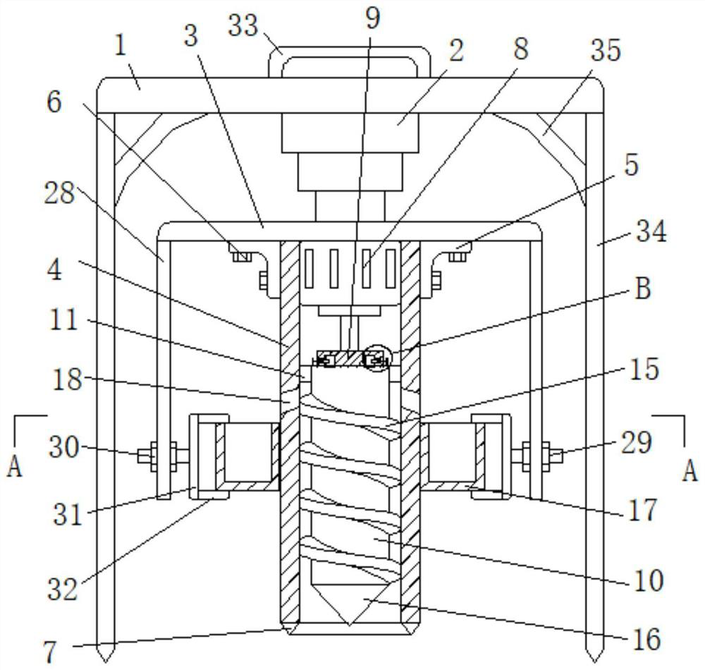
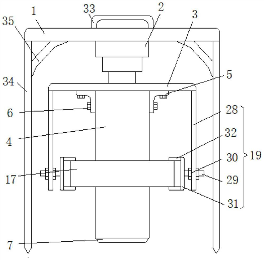
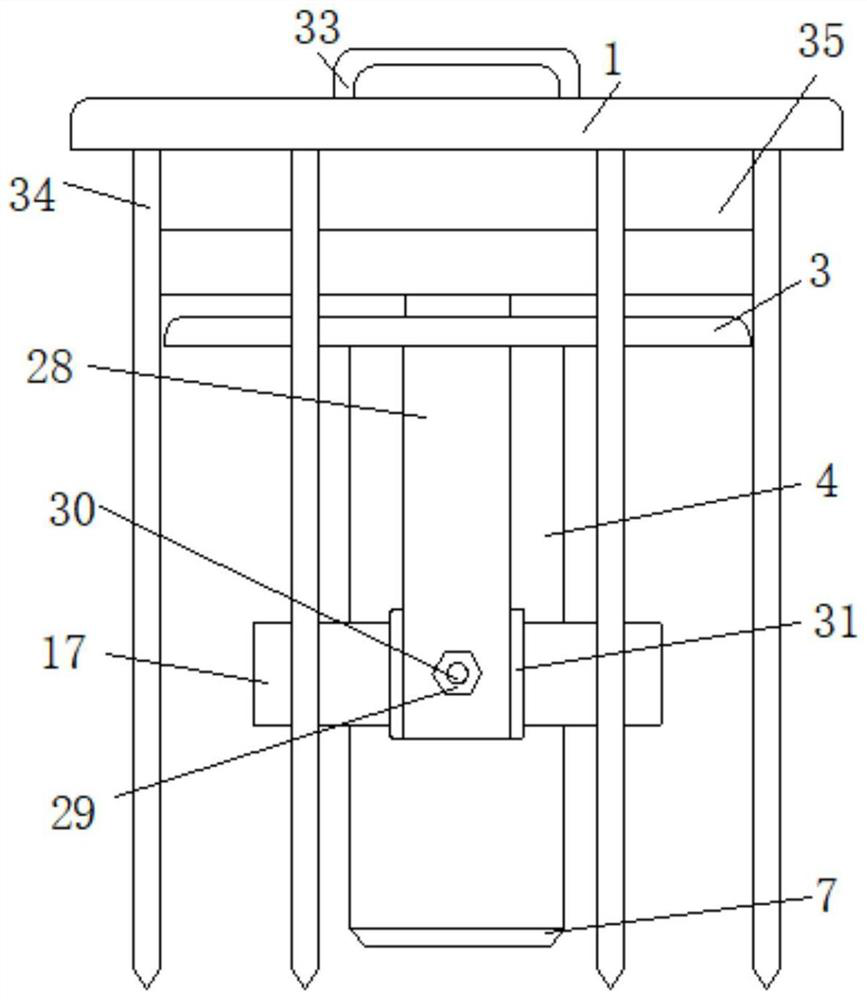
[0030] Embodiment one, such as Figure 1-7As shown, a sampler for soil detection based on environmental detection includes a horizontally arranged substrate 1, a cylinder 2 is fixedly connected to the bottom surface of the substrate 1, and a first connecting plate 3 arranged horizontally is fixedly connected to the bottom end of the cylinder 2. The bottom of the connecting plate 3 is provided with a material taking tube 4, the top of the material taking tube 4 is in contact with the bottom surface of the first connecting plate 3, and a plurality of connecting pieces 5 are arranged on the outside of the taking material tube 4, the cross section of the connecting piece 5 is L-shaped, the first Both the connecting plate 3 and the retrieving cylinder 4 are in contact with the connecting piece 5, the first connecting plate 3 and the retrieving cylinder 4 are fixedly connected to the connecting piece 5 through the mounting screw 6, and the bottom end of the taking cylinder 4 is fixed...

Embodiment 2

[0031] Embodiment two, such as figure 1 , 6 , 7, the clamping mechanism 14 includes a groove 20 arranged in the clamping groove 13, a sliding plate 21 is slidably connected to the groove 20, and a locking block 22 is fixedly connected to the side of the sliding plate 21 facing the port of the groove 20, The side of the sliding plate 21 facing away from the port of the groove 20 is fixedly connected with a first pull rod 23, and the first pull rod 23 is arranged horizontally. The outer part of the second connecting plate 9 is fixedly connected with a second pull rod 24, the second pull rod 24 is vertically arranged, and the side of the sliding plate 21 facing away from the port of the groove 20 is fixedly connected with the inner wall of the groove 20 by a spring 25, and the clamping column 12 There is a card slot 26 that matches the block 22, and the inner port of the groove 20 is fixedly connected with a limiter 27. The limiter 27 is ring-shaped, and the limiter 27 is sleeve...

Embodiment 3

[0032] Embodiment three, such as Figure 1-5 As shown, the fixing mechanism 19 includes a support plate 28 fixedly connected to the bottom surface of the first connecting plate 3, the support plate 28 is vertically arranged, and the bottom end of the support plate 28 is horizontally provided with a screw rod 29, and the screw rod 29 runs through the support plate 28 and is slidably connected with it. , both sides of the support plate 28 are provided with nuts 30, and the two nuts 30 are threadedly connected with the screw rod 29, and the two nuts 30 are in contact with the support plate 28, and the end of the screw rod 29 near the receiving tube 17 is fixedly connected with a first abutment plate 31, the first abutment plate 31 is vertically arranged, the upper and lower ends of the inner side of the first abutment plate 31 are fixedly connected with the second abutment plate 32, and the two second abutment plates 32 are all arranged horizontally, and the second abutment plate ...


PUM


Abstract

The invention discloses a soil detection sampler based on environmental detection. The soil detection sampler comprises a horizontally-arranged substrate, wherein the bottom surface of the substrate is fixedly connected with an air cylinder, the bottom end of the air cylinder is fixedly connected with a horizontally-arranged first connecting plate, a material taking cylinder is arranged below thefirst connecting plate, the top end of the material taking cylinder abuts against and makes contact with the bottom face of the first connecting plate, a plurality of connecting pieces are arranged onthe outer side of the material taking cylinder, the sections of the connecting pieces are in an L shape, the first connecting plate and the material taking cylinder both abut against and make contactwith the connecting pieces, and the first connecting plate and the material taking cylinder are both fixedly connected with the connecting pieces through mounting screws. A sampling assembly is pressed into a soil layer through the air cylinder, meanwhile, a motor drives a material taking roller and a material taking device to rotate, crushed soil is conveyed into a material collecting barrel upwards, semi-automatic taking and culturing are achieved, convenience and rapidness are achieved, meanwhile, the multiple core assemblies of the device are detachably connected, therefore the material taking roller is convenient to detach and clean, the next soil sampling is not influenced, and the practicability is high.

Description

technical field [0001] The invention relates to the technical field of soil sampling devices, in particular to a soil detection sampler based on environmental detection. Background technique [0002] A soil sampler is a tool used to obtain soil samples. Commonly used are soil drills, shovels and shovels. The soil drills are composed of drill bits and handles made of hard materials (steel or hard plastic). The drill bits are usually helical or cylindrical. The top of the helical drill is a pair of rotatable The sharp knife edge that cuts into the soil, followed by an enlarged soil-filled cavity, drills down into the soil surface with the rotation of the handle, and the soil sample to be collected in the soil layer can be introduced into the cavity. The diameter of the cylindrical soil drill is at both ends There is a slight difference, the end connected to the handle is slightly larger than the end that is in contact with the soil, to ensure that the soil that has entered th...

Claims


Application Information

Patent Timeline
Patent Type & Authority Applications(China)
IPC IPC(8): G01N1/08
CPCG01N1/08
Inventor 刘杨
Owner 刘 杨
Why Eureka
Try Eureka