Optical fiber light supply equipment

A technology of optical fiber and optical equipment, applied in the direction of optical guide, optical waveguide coupling, optics, etc., can solve the problems of test optical parameter deviation, blurred light, etc., and achieve the effect of reducing deviation, clear light, and speeding up temperature drop

Inactive Publication Date: 2020-12-25
杨晓盼
View PDF0 Cites 0 Cited by
  • Summary
  • Abstract
  • Description
  • Claims
  • Application Information

AI Technical Summary

Problems solved by technology

[0002] Due to the reflectivity of the optical fiber, the optical fiber has a wide range of applications in various fields. In the process of studying the lighting characteristics inside the mining area, due to the harsh environment inside the mining area, the staff cannot reach around the light source, and light supply equipment is usually used to provide light. , the light energy is injected into the optical fiber of the optical fiber sensor, and the light energy is transmitted to the electric device through the reflection of the optical fiber to test the parameters of the light; in the prior art, the optical fiber sensor is used to test the parameters of the light during the test process, due to the low temperature inside the mine, the photoreceptor The temperature of the lens decreases, and the temperature inside the sensor increases through the current, the air inside the sensor is easily liquefied and becomes water mist on the inner wall of the lens, resulting in blurred light acquired by the sensor, resulting in deviations in the parameters of the test light

Method used


Image

  • Optical fiber light supply equipment
  • Optical fiber light supply equipment
  • Optical fiber light supply equipment

Examples


Embodiment 1

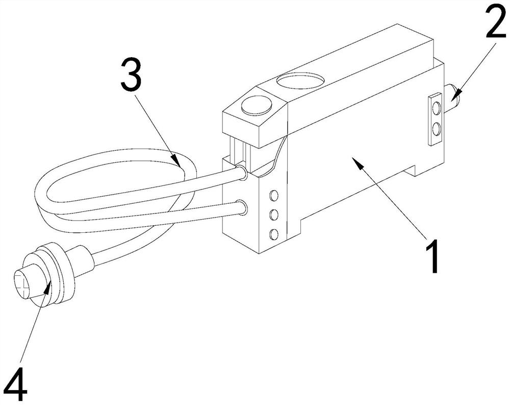
[0025] as attached figure 1 to attach Figure 5 Shown:

[0026] The invention provides an optical fiber light supply device, the structure of which includes an electrical device 1, a port 2, a wire 3, and a photoreceptor 4, the right side of the electrical device 1 is provided with a port 2, and the wire 3 is installed on the electrical device 1 On the left side, the photoreceptor 4 is connected to the end of the photoreceptor 4 .

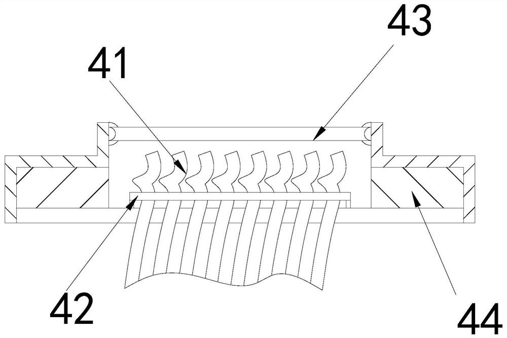
[0027] The photoreceptor 4 is provided with an optical fiber 41, a binding block 42, a lens 43, and a cooling block 44. The optical fiber 41 passes through the bottom of the photoreceptor 4 and is located inside the photoreceptor 4. The binding block 42 is bound on the light guide Outside the fiber 41 , the lens 43 is fixed on the top of the middle part of the photoreceptor 4 , and the heat dissipation block 44 is located inside the photoreceptor 4 and on both sides of the optical fiber 41 .

[0028] Wherein, the heat dissipation block 44 is pro...

Embodiment 2

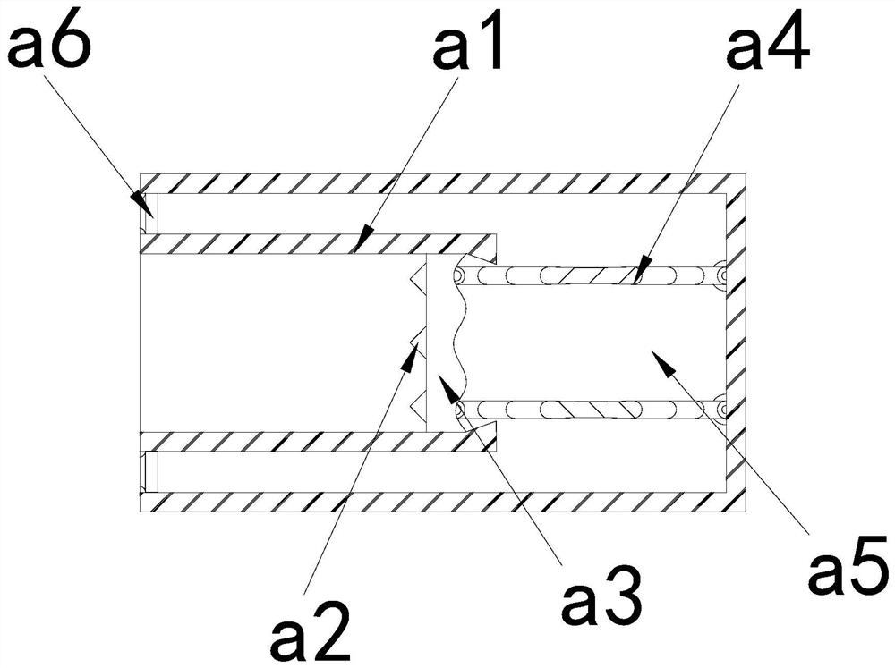
[0034] as attached Figure 6 to attach Figure 7 Shown:

[0035] Wherein, the air inlet s4 is provided with a side plate n1, a splint n2, an inner cavity n3, a connecting plate n4, an air hole n5, and a push spring n6, the side plate n1 is located on the left side of the air inlet s4, and the splint n2 is installed At the upper and lower ends of the side plate n1, the inner cavity n3 is located inside the air inlet s4, the splint n2 is movably matched through the connecting plate n4, the air hole n5 runs through both sides of the connecting plate n4, and the push spring n6 is clamped in the air hole Between n5, the connecting plate n4 has elasticity, which is beneficial to drive the splint n2 to swing, so that the gas in the inner cavity n3 is pressurized and the impact force of the gas is increased.

[0036]Wherein, the splint n2 is provided with a bottom plate m1, an inner groove m2, a partition m3, and a clamping ball m4. Fixed on the inner wall of the inner groove m2, t...


PUM


Abstract

The invention discloses optical fiber light supply equipment. The optical fiber light supply equipment structurally comprises an electric device, a port, a wire and a photoreceptor; the port is formedin the right side of the electric device, and the wire is installed on the left side of the electric device. Due to the fact that the temperature of a lens of the photoreceptor is reduced and the temperature of current inside an inductor is increased, and air inside the inductor is easily liquefied into water mist on the inner wall of the lens; and through repeated back-and-forth movement of a push plate inside a heat dissipation block, gas inside a gas cavity is extruded to diffuse to a diffusion device, air flow speed inside the photoreceptor is accelerated, air liquefaction inside the lensis reduced, clear light acquired by the inductor is facilitated, and parameter deviation of test light is reduced. Due to the fact that when the amount of gas passing through a gas inlet is small, the flow rate of the gas is reduced, and the gas in an inner cavity is pressurized through swinging of a clamping plate, so that the pressure of the gas is increased, and the impact force is increased along with the increase of the pressure of the gas, dispersion of the gas through a diffusion block is accelerated, the diffusion area of the gas is increased, and the temperature reduction inside thephotoreceptor is accelerated.

Description

technical field [0001] The invention belongs to the field of optical fiber equipment, and more specifically relates to an optical fiber light supply equipment. Background technique [0002] Due to the reflectivity of the optical fiber, the optical fiber has a wide range of applications in various fields. In the process of studying the lighting characteristics inside the mining area, due to the harsh environment inside the mining area, the staff cannot reach around the light source, and light supply equipment is usually used to provide light. , the light energy is injected into the optical fiber of the optical fiber sensor, and the light energy is transmitted to the electric device through the reflection of the optical fiber to test the parameters of the light; in the prior art, the optical fiber sensor is used to test the parameters of the light during the test process, due to the low temperature inside the mine, the photoreceptor The temperature of the lens decreases, and t...

Claims


Application Information

Patent Timeline
Patent Type & Authority Applications(China)
IPC IPC(8): G02B6/26G02B6/42
CPCG02B6/262G02B6/4269
Inventor 杨晓盼
Owner 杨晓盼
Why Eureka
Try Eureka