
A device and experimental method suitable for calibrating the daily difference of quartz electronic stopwatches

A stopwatch and electronic technology, applied in the field of stopwatch detection, can solve the problems of inconvenient operation process, high instrument cost, easy to be interfered, etc., and achieve the effect of convenient operation process, high test accuracy and low manufacturing cost

Active Publication Date: 2022-02-08
徐州市质量技术监督综合检验检测中心
View PDF14 Cites 0 Cited by
  • Summary
  • Abstract
  • Description
  • Claims
  • Application Information

AI Technical Summary

Problems solved by technology

In the prior art, it is recommended to use a daily difference calibrator for the verification of the daily difference, but because the traditional daily difference calibrator uses electromagnetic induction for detection operations, it is easy to be interfered, and the operation process is very inconvenient. At the same time, the instrument cost Therefore, most of the stopwatches did not use the daily difference calibrator to test the accuracy when they built the standard. Instead, they chose the calibration method of 1-day upward travel time for detection. This method is extremely time-consuming. In the actual operation process, unless it is necessary, the general stopwatch test should try to avoid the daily difference test
[0004] To sum up, the existing testing equipment is poor in terms of testing accuracy, operation convenience, manufacturing cost and time-consuming, and cannot meet the actual testing needs, and cannot effectively monitor the daily difference of the quartz electronic stopwatch. test

Method used


Image

  • A device and experimental method suitable for calibrating the daily difference of quartz electronic stopwatches
  • A device and experimental method suitable for calibrating the daily difference of quartz electronic stopwatches
  • A device and experimental method suitable for calibrating the daily difference of quartz electronic stopwatches

Examples


Embodiment Construction

[0032] The present invention will be further described below in conjunction with accompanying drawing.

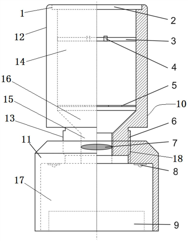
[0033] Such as Figure 1 to Figure 4 As shown in the present invention, a device suitable for calibrating the daily difference of a quartz electronic stopwatch includes a light-tight housing, an optical imaging assembly, a photoelectric sampling unit 4 and a plurality of supplementary lighting lamps 8; the optical imaging assembly It includes an observation screen 3, a diaphragm 5, a lens 7 and a focusing sleeve 6 arranged concentrically;

[0034] The housing is composed of an upper cylindrical housing 10 and a lower cylindrical housing 11 arranged concentrically;

[0035] The upper cylindrical housing 10 includes a large diameter section 12 and a small diameter section 13 coaxially arranged up and down, and a large cylindrical inner cavity 14 and a small diameter section 14 coaxially provided are respectively opened inside the large diameter section 12 and the small diame...


PUM


Abstract

A device and experimental method suitable for calibrating the daily difference of a quartz electronic stopwatch. The shell is composed of an upper and a lower cylindrical shell; section, the upper ends of the large and small cylindrical inner cavities are connected through an inverted frustum-shaped inner cavity at the junction of the large and small diameter sections; the upper end of the large diameter section is provided with a mounting notch, and an observation cover is provided at the installation notch plate; the observation screen and diaphragm are installed at the upper and lower ends of the large cylindrical cavity; the lens is installed in the small cylindrical cavity; the photoelectric sampling unit is set at the center of the viewing screen; cavity, and a communication hole is opened in the center of the upper end; the focusing sleeve is fixedly inserted into the communication hole, and it is connected to the outside of the small diameter section through thread fit; multiple supplementary lighting lamps are installed on the top of the cylindrical accommodation cavity. The device and method have high testing precision and convenient operation process, and can quickly and effectively complete the verification of daily difference.

Description

technical field [0001] The invention belongs to the technical field of stopwatch detection, in particular to a device and an experimental method suitable for calibrating the daily difference of a quartz electronic stopwatch. Background technique [0002] Time is one of the most important parameters in nature. With the advancement of measurement technology, the measurement of time intervals is widely used in all aspects of production and life, and the timing methods are also changing with each passing day. Therefore, the measurement of time intervals is also an indispensable testing item for various measurement technical institutions. [0003] The timing reference of most timers comes from the internal quartz crystal oscillator, and the stability of ordinary non-temperature-controlled quartz crystal oscillators can reach 10 -6 The order of magnitude has high requirements for measurement. At this stage, it is usually required to test the accuracy and stability of the interna...

Claims


Application Information

Patent Timeline
Patent Type & Authority Patents(China)
IPC IPC(8): G04D7/00
CPCG04D7/00
Inventor 许晓晨杨建军王磊陈曦倪浩然张坤朱本龙
Owner 徐州市质量技术监督综合检验检测中心
Learn More