
Crimping die machine cable crimping process

A technology for crimping dies and cables, which is applied in the direction of connection and connection by deformation, assembly/disassembly of vehicle connectors and contacts, etc., which can solve the problems of difficult installation, unsatisfactory electrical performance, high-voltage arc fire, etc., to avoid flying edge effect

Active Publication Date: 2020-12-25
CRRC TANGSHAN CO LTD
View PDF5 Cites 3 Cited by
  • Summary
  • Abstract
  • Description
  • Claims
  • Application Information

AI Technical Summary

Problems solved by technology

[0004] The purpose of the present invention is to provide a crimping die, aiming to solve the problem that after the cable and the terminal are crimped, burrs are easy to appear, which makes installation difficult, the electrical performance cannot meet the requirements, and even high-voltage arcs cause fires.

Method used

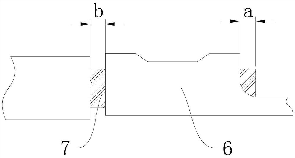

Image

  • Crimping die machine cable crimping process
  • Crimping die machine cable crimping process
  • Crimping die machine cable crimping process

Examples


Embodiment Construction

[0032] In order to make the technical problems, technical solutions and beneficial effects to be solved by the present invention clearer, the present invention will be further described in detail below in conjunction with the accompanying drawings and embodiments. It should be understood that the specific embodiments described here are only used to explain the present invention, not to limit the present invention.

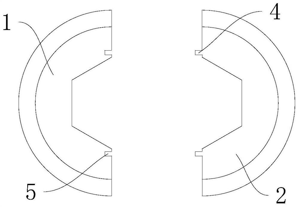
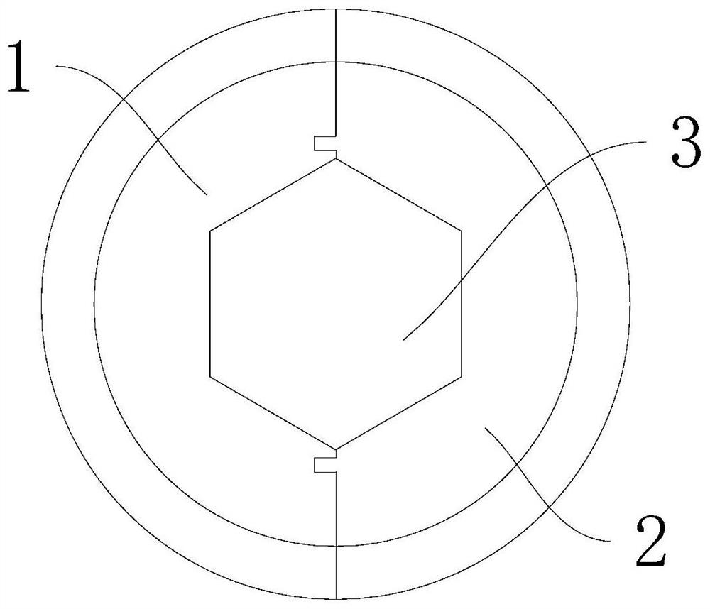
[0033] A crimping die provided by the present invention will now be described. see Figure 1 to Figure 2 , a crimping mold, including a first tire mold 1, a second tire mold 2, a block 4 and a slot 5.

[0034] The second tire mold 2, the first tire mold 1 and the second tire mold 2 are attached to each other to form a crimping cavity 3 for crimping the terminal 6; Both sides are used to prevent the crimping flash from extending outward; the slot 5 is arranged on the second tire mold 2 to cooperate with and accommodate the stopper 4; when the first tire mold 1 and...


PUM


Abstract

The invention provides a crimping die and a cable crimping process, and belongs to the technical field of crimping, the crimping die comprises a first forming die, a second forming die, stop blocks and a slot, and the first forming die and the second forming die are attached to each other to form a crimping cavity for crimping a wiring terminal; the stop blocks are arranged on the first moulding bed, are positioned on the two sides of the crimping cavity and are used for preventing the crimping flash from extending outwards; the slot is formed in the second forming die and used for containingthe stop blocks in a matched mode; and when the first forming die and the second forming die extrude the wiring terminal, the stop blocks are inserted into the slot, and the stop blocks, the first forming die and the second forming die form an accommodating space for accommodating the crimping wiring terminal. The crimping die is adopted in the cable crimping process, and according to the crimpingdie provided by the invention, the wiring terminal is extruded to generate an extension trend between the first forming die and the second forming die, and is blocked by the stop blocks, so that thegeneration of flash is effectively avoided.

Description

technical field [0001] The invention belongs to the technical field of crimping, and more specifically relates to a crimping die and a cable crimping process using the crimping die. Background technique [0002] If the vehicle is the human body, the cables are the nerves and blood vessels. With the continuous development of rail vehicles, cables, as the medium and carrier of transmission, have higher quality requirements. A cable is usually composed of a cable and terminals at both ends, and the electrical connection between the cable and the terminals directly determines the transmission performance of the cable. In the rail vehicle production industry, the electrical connection between the cable and the terminal block is achieved by means of a crimp connection. The quality of the crimping will directly affect the electrical and mechanical properties of the vehicle electrical system, and ultimately affect the operating safety and service life of the vehicle. [0003] To ...

Claims


Application Information

Patent Timeline
Patent Type & Authority Applications(China)
IPC IPC(8): H01R43/05H01R43/20
CPCH01R43/05H01R43/20H01R2201/26
Inventor 赵丽娜黄少东曹开源徐世木李文娟
Owner CRRC TANGSHAN CO LTD
Learn More