An impeller structure for cooking equipment and an oven with the structure

A technology of cooking equipment and impeller, applied in the field of impeller structure and oven, can solve the problems of inferior two-way non-angle fan blades, inferior uniformity of temperature field in the oven inner tank, etc., and achieve the effect of good airflow uniformity

Active Publication Date: 2021-07-23
NINGBO FOTILE KITCHEN WARE CO LTD
View PDF1 Cites 0 Cited by
  • Summary
  • Abstract
  • Description
  • Claims
  • Application Information

AI Technical Summary

Problems solved by technology

[0004] Among them, the temperature field uniformity of the one-way fixed-angle fan blade on the oven liner is not as good as the comprehensive effect of the forward and reverse rotation of the two-way non-angle fan blade, and the two-way non-angle fan blade is not as good as the one-way fixed-angle fan blade when rotating in one direction fan blade

Method used


Image

  • An impeller structure for cooking equipment and an oven with the structure
  • An impeller structure for cooking equipment and an oven with the structure
  • An impeller structure for cooking equipment and an oven with the structure

Examples


Embodiment 1

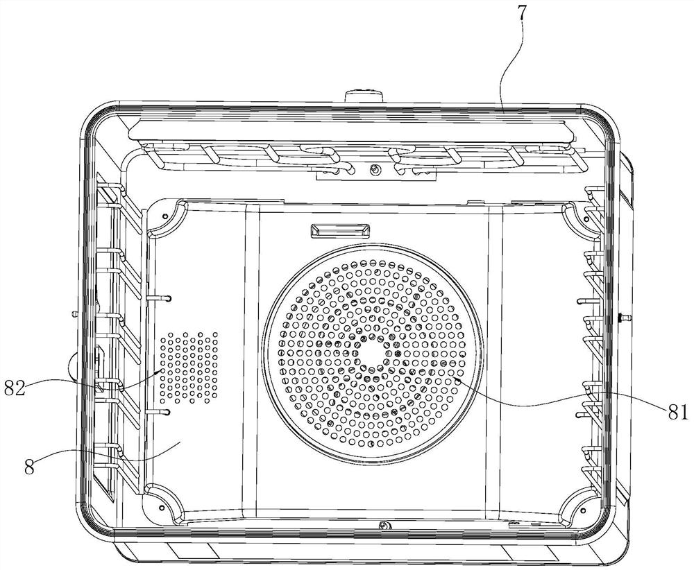
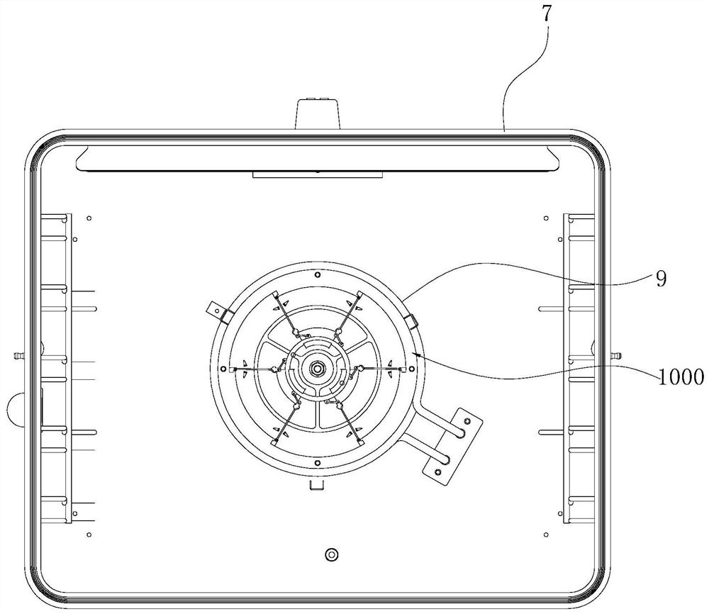
[0038] Such as Figure 1-5 As shown, a kind of oven comprises liner 7, and the rear side of this liner 7 is vertically provided with hot air baffle 8 with air inlet 81 and air outlet 82, and this hot air baffle 8 is surrounded by the back plate of liner 7 A hot air chamber 80 is formed, and an impeller structure 1000 is arranged in the hot air chamber 80 , and a back heating pipe 9 is arranged around the outer periphery of the impeller structure 1000 . When the oven works like this, the impeller structure 1000 rotates under the drive of the motor, and the cold air in the inner container 7 is sucked in the hot air chamber 80 through the air inlet 81 on the hot air baffle 8, and the hot air heated by the back heating tube 9 is in the oven. Under the action of the centrifugal force of the impeller structure 1000, it flows back into the inner container 7 through the air outlet 82 of the hot air baffle 8, and is used for toasting the food in the inner container 7, such as Figure ...

Embodiment 2

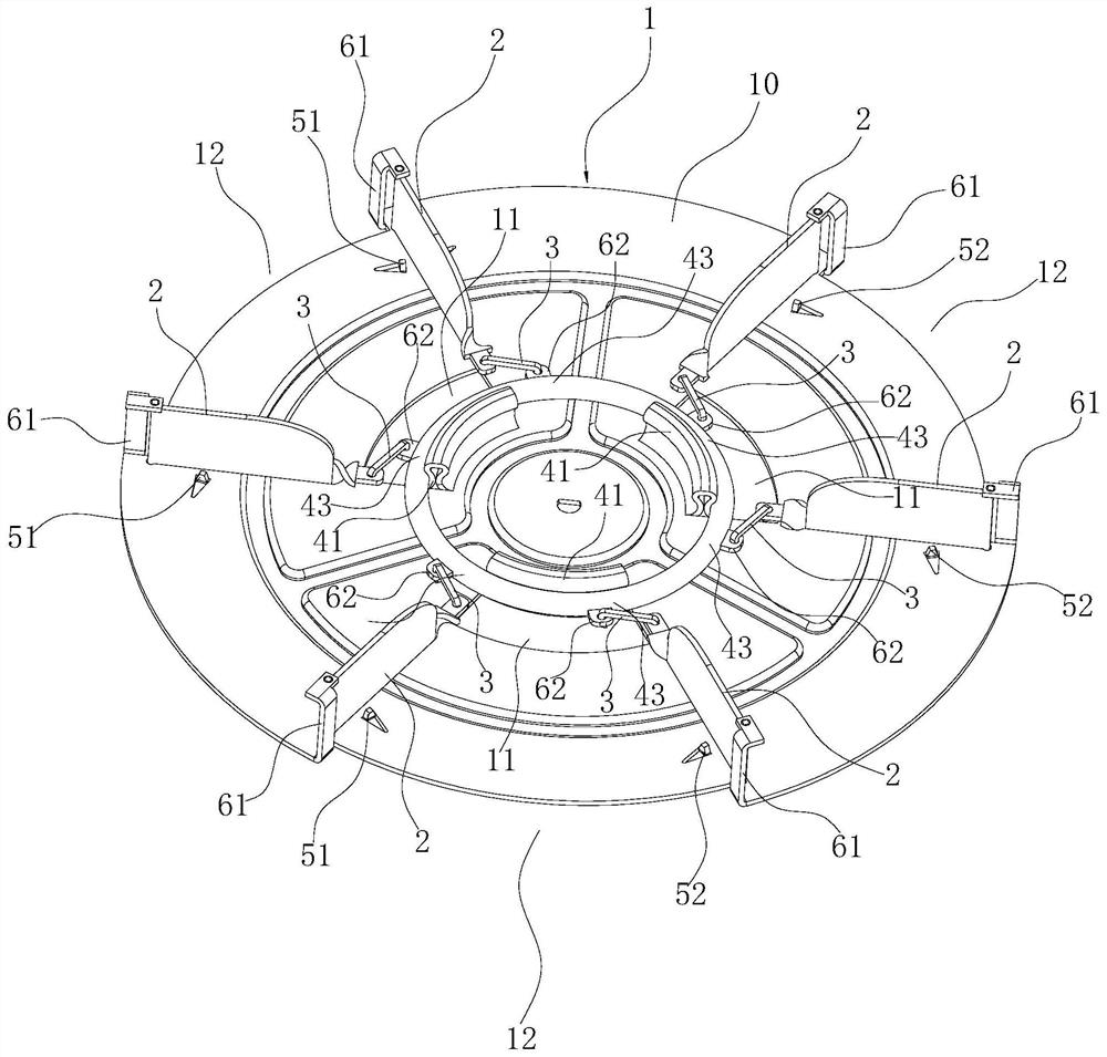
[0051] Such as Figure 6-9 As shown, the difference from Embodiment 1 is that in this embodiment, the above-mentioned sliding structures correspond to two adjacent fan blades 2 respectively, and each sliding structure 4 includes a The arc-shaped second slide rail 42 and the slide seat 44 that can slide along the second slide rail 42, the second hinge seats 62 of two adjacent fan blades 2 are respectively connected with the slide seat 44, each second slide rail 42 each extend along the aforementioned trajectory circle 100 . Arranging two adjacent fan blades 2 on one sliding seat 44 can improve the efficiency of adjusting the angle of the fan blades 2, and the two fan blades 2 on the same sliding seat 44 and the corresponding connecting rod 3 have different structures and are dead at the same time. point (that is, the angle α formed by the fan blade 2 and the corresponding connecting rod 3 is equal to 180°), so as to ensure that the angle of the fan blade 2 is automatically adj...


PUM


Abstract

The invention relates to an impeller structure for cooking equipment, which comprises a disc-shaped main board, fan blades are arranged at intervals along the circumferential direction on the first disc surface of the main board, and each fan blade has a strip shape and is opposite to the The main board extends along the inner and outer directions and is arranged perpendicular to the first disk surface. The outer peripheral side of the first disk surface of the above-mentioned main board is provided with first hinge seats corresponding to the above-mentioned fan blades at intervals along the circumferential direction, and also includes the first hinge seats corresponding to the above-mentioned fan blades. One-to-one corresponding connecting rods, the first end of each fan blade is respectively rotatably connected with the corresponding first hinge seat and the second end is respectively rotatably connected with the first end of the corresponding connecting rod, and the second ends of each connecting rod are It is located on a track circle centered on the center of the above-mentioned first disk surface and can slide along the track circle circumferentially, and the track circle is located in the middle of the above-mentioned first disk surface. Compared with the prior art, the present invention can change the angle of the fan blade according to its rotation direction, so that the impeller structure can obtain better airflow uniformity in both forward rotation and reverse rotation states.

Description

technical field [0001] The invention relates to the field of cooking equipment, in particular to an impeller structure for cooking equipment and an oven with the structure. Background technique [0002] Cooking equipment with baking functions such as electric ovens are generally provided with a hot air baffle on the rear side of the inner tank. The hot air baffle and the back plate of the inner tank form a hot air chamber. The outer periphery of the leaf is provided with a back heating pipe. In this way, when the oven is working, the fan blades rotate, and the cold air in the inner tank is sucked into the hot air chamber through the air inlet on the hot air baffle, and the hot air heated by the back heating tube passes through the hot air baffle under the centrifugal force of the fan blades. The air outlet of the plate is returned to the inner container for toasting the food in the inner container. [0003] Existing ovens generally use one-way fixed-angle fan blades or two...

Claims


Application Information

Patent Timeline
Patent Type & Authority Patents(China)
IPC IPC(8): A47J37/06
CPCA47J37/0641A47J37/0664
Inventor 谭万福王丁姚青
Owner NINGBO FOTILE KITCHEN WARE CO LTD
Why Eureka
Try Eureka