Device for Improving Airflow Uniformity in Aircraft Experimental Wind Tunnel and Its Parameter Optimization Method

A uniformity and wind tunnel technology, which is applied in the field of devices for improving the airflow uniformity of aircraft experimental wind tunnels, can solve the problems of large wind speed unevenness, low airflow uniformity, and unfavorable aircraft blowing, and achieves increased airflow uniformity and interference. The effect of reducing the degree of turbulence and reducing the degree of turbulence

Active Publication Date: 2022-03-15
CHINA AIRPLANT STRENGTH RES INST
View PDF14 Cites 0 Cited by
  • Summary
  • Abstract
  • Description
  • Claims
  • Application Information

AI Technical Summary

Problems solved by technology

[0005] The technical problem solved by the present invention is: in the prior art, the wind speed of the aircraft wind tunnel laboratory is small, the uniformity of the airflow is low, and the unevenness of the wind speed in the effective area is relatively large, which is not conducive to the carrying out of the aircraft blowing experiment

Method used


Image

  • Device for Improving Airflow Uniformity in Aircraft Experimental Wind Tunnel and Its Parameter Optimization Method
  • Device for Improving Airflow Uniformity in Aircraft Experimental Wind Tunnel and Its Parameter Optimization Method
  • Device for Improving Airflow Uniformity in Aircraft Experimental Wind Tunnel and Its Parameter Optimization Method

Examples


Embodiment 1

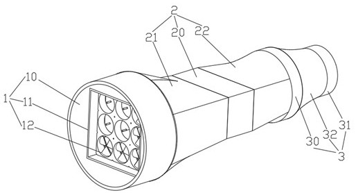
[0051] Such as figure 2A device for improving airflow uniformity in an aircraft experimental wind tunnel is shown, including a power section 1, a steady flow adjustment section 2, and a contraction section 3;

[0052] The power section 1 includes a tubular power body section 10, a fan installation structure 11 arranged in the power body section 10, and 3 rows of fans 12 arranged in a matrix on the fan installation structure 11;

[0053] The steady flow adjustment section 2 includes a turbulent flow adjustment section 20 communicated with the power body section 10, a first variable-section connection section 21 that communicates with the power main body section 10 and the other end communicates with the turbulence adjustment section 20, and communicates with the turbulence section 20. The flow adjustment section 20, the second variable section connection section 22 of the constriction section 3;

[0054] The central axes of the power body section 10, the first variable-sectio...

Embodiment 2

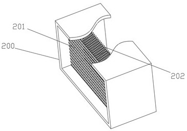
[0075] Different from Embodiment 1, the ratio of the diagonal length A of the rectangular section of the rectangular duct 200 to the diameter D of the main power section 10 is 4.2:5;

[0076] The ratio of the diameter d of the large diameter connecting pipe 30 to the diameter D of the main power section 10 is 3.9:5;

[0077] The height of the windward end of the rectifying vane 310 is 18.5 cm; the length of the rectifying vane 310 is 120 cm.

Embodiment 3

[0079] A device for improving airflow uniformity in an aircraft experimental wind tunnel, comprising a power section 1, a steady flow adjustment section 2, and a contraction section 3;

[0080] The power section 1 includes a tubular power body section 10, a fan installation structure 11 arranged in the power body section 10, and four rows of fans 12 arranged in a matrix on the fan installation structure 11;

[0081] The steady flow adjustment section 2 includes a turbulent flow adjustment section 20 communicated with the power body section 10, a first variable-section connection section 21 that communicates with the power main body section 10 and the other end communicates with the turbulence adjustment section 20, and communicates with the turbulence section 20. The flow adjustment section 20, the second variable section connection section 22 of the constriction section 3;

[0082] The central axes of the power body section 10, the first variable-section connecting section 21...


PUM


Abstract

The invention relates to the technical field of airflow uniformity in wind tunnel experiments, and discloses a device for improving airflow uniformity in an aircraft experiment wind tunnel and a parameter optimization method thereof; the device includes a power section, a steady flow adjustment section and a contraction section; the power section includes a circular tubular power The main body section, the fan installation structure arranged in the power main section, and the fan installed on the fan installation structure; the method includes: S1, initially setting size parameters; S2, modeling the whole wind tunnel; S3, performing fluid simulation; S4. Determine whether the unevenness of wind speed in the target area is less than 5%; if the unevenness is less than 5%, the design is completed; if it is not less than 5%, then modify the size parameters of step S1 and repeat steps S2~S4; the present invention can meet the needs of large aircraft. The wind tunnel test requires large air volume and high wind speed; it can improve the uniformity of airflow.

Description

technical field [0001] The invention relates to the technical field of aircraft testing, in particular to a device for improving airflow uniformity in an aircraft experimental wind tunnel and a parameter optimization method thereof. Background technique [0002] Wind tunnel testing in fluid mechanics refers to an aerodynamic experimental method that places aircraft or other object models in a wind tunnel to study gas flow and its interaction with the model to understand the aerodynamic characteristics of actual aircraft or other objects. [0003] When the blowing test is carried out in the aircraft wind tunnel laboratory, the wind speed is high, and the maximum wind speed requirement is 60m / s; the uniformity requirement is high, and the blowing effective area of ​​the wind tunnel system at 4m downstream from the air outlet is not less than 1m 2 (Height × width = 1m × 1m), unevenness within the effective area ≤ ± 5%. To meet the requirement of high wind speed, it is necessar...

Claims


Application Information

Patent Timeline
Patent Type & Authority Patents(China)
IPC IPC(8): G01M9/04G01M9/08B64F5/60G06F30/23G06F30/28G06F113/08G06F119/14
CPCG01M9/04G01M9/08B64F5/60G06F30/23G06F30/28G06F2113/08G06F2119/14
Inventor 吴敬涛成竹任战鹏李剑张亚娟
Owner CHINA AIRPLANT STRENGTH RES INST
Why Eureka
Try Eureka