Linear forging and pressing transporter

A handling machine and forging technology, applied in forging/pressing/hammering machinery, forging/pressing/hammer devices, manufacturing tools, etc., can solve the problems of inconvenient handling, small contact area, unbalanced gravity on both sides, etc. The effect of transport

Inactive Publication Date: 2020-12-29
张志杰
View PDF0 Cites 0 Cited by
  • Summary
  • Abstract
  • Description
  • Claims
  • Application Information

AI Technical Summary

Problems solved by technology

[0005] Aiming at the deficiencies in the prior art, the purpose of the present invention is to provide a linear forging transfer machine to solve the problem that in the prior art, the forging of the thin sheet metal parts will cause the metal parts to plastically deform outwards and expand outwards. Make the outer contour of the metal parts form irregular protrusions, and then in the process of plane clamping and handling, the contact area is small to form a fulcrum, and the gravity on both sides is unbalanced, which affects the rotation of the metal parts around the clamping plate. Problems that cause inconvenience in transportation

Method used


Image

  • Linear forging and pressing transporter
  • Linear forging and pressing transporter
  • Linear forging and pressing transporter

Examples


Embodiment 1

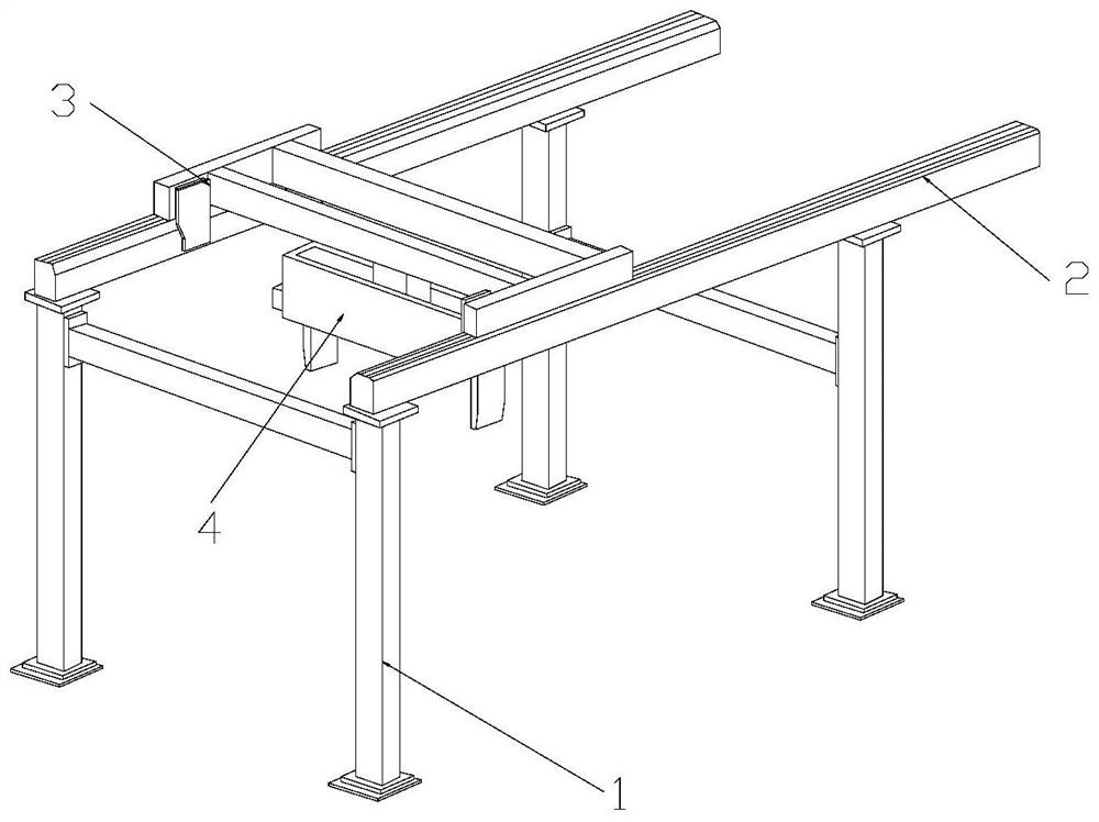
[0028] Example 1: Please refer to Figure 1-Figure 6 , the specific embodiments of the present invention are as follows:

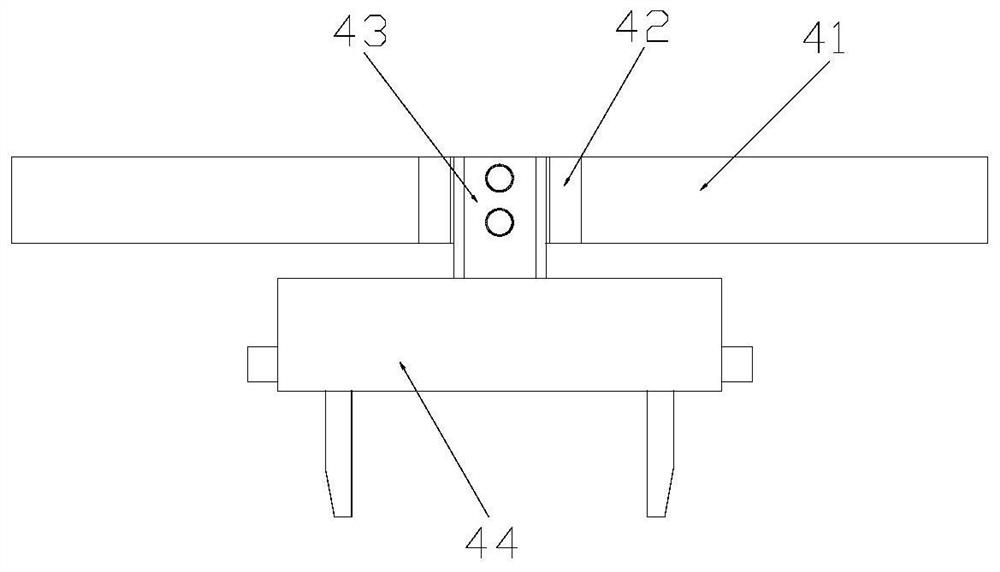
[0029] Its structure includes a support frame 1, a guide rail 2, a moving seat 3, and a handling structure 4. The guide rail 2 is horizontally installed on the upper end of the support frame 1 and welded to each other. The transport structure 4 is horizontally installed between the moving seats 3 and is fixedly connected; the transport structure 4 includes a horizontal frame 41, a limiting plate 42, a fixed rod 43, and a clamping structure 44, and the limiting plate 42 is located on the The inner side of the horizontal frame 41 is an integrated structure. The fixed rod 43 is fixed on the inner side of the horizontal frame 41 by bolts and is limited between the limit plates 42. The fixed rod 43 is vertically installed on the upper end of the clamping structure 44 and welded.

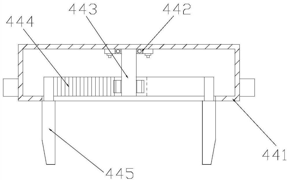
[0030] refer to image 3 The clamping structure 44 includes a chassis 441, a mo...

Embodiment 2

[0036] Example 2: Please refer to Figure 5 , Figure 7-Figure 8 , the specific embodiments of the present invention are as follows:

[0037] The movable structure 45c includes a fixed shaft c1, a rotating structure c2, a friction block c3, a plate body c4, and an adapting structure c5. The fixed shaft c1 runs through the inner side of the rotating structure c2 and adopts a flexible connection. The fixed shaft c1 is fixedly connected to The inner side of the fixed plate 45a, the plate body c4 is vertically installed on the lower end of the rotating structure c2 and welded together, the friction block c3 is arranged on the outside of the front surface of the plate body c4 and is an integrated structure, and the adaptable structure c5 is embedded and installed on the plate body c4 inside and located inside the friction block c3.

[0038] refer to Figure 5 , the adapting structure c5 is obliquely installed inside the board c4, the movable angle between the adapting structure ...


PUM


Abstract

The invention discloses a linear forging and pressing transporter. The linear forging and pressing transporter structurally comprises a supporting frame, guide rails, moving seats and a handling structure. The guide rails are horizontally installed at the upper end of the supporting frame, the moving seats are installed on the inner sides of the upper ends of the guide rails in an embedded manner,and the handling structure is horizontally installed between the moving seats and comprises a transverse frame, limiting plates, a fixed rod and a clamping structure. The limiting plates are arrangedon the inner side of the transverse frame and are of an integrated structure, the fixed rod is fixed to the inner side of the transverse frame through a bolt and limited between the limiting plates,and the fixed rod is perpendicularly installed at the upper end of the clamping structure and welded to the clamping structure. According to the linear forging and pressing transporter, the clamping structure is arranged at the lower end of the fixed rod, contact with a metal workpiece is increased, adaptation supporting is carried out better, and deviation and rotation in the handling process areprevented; and an adaptation structure is arranged on the outer side of a plate body, multi-point respective adaptation limitation is carried out, the influence of gravity is adopted in cooperation to better clamp the metal workpiece, and handling of the metal workpiece is facilitated.

Description

technical field [0001] The invention belongs to the field of forging, and in particular relates to a linear forging transfer machine. Background technique [0002] Forging is mainly forging and stamping. It mainly uses forging machinery to forge the blank to form the required shape and size. Forging is mainly used for forging of metal parts. During the forging process, multiple stampings are required. Metal parts undergo multiple plastic deformations, and during this process, the metal parts need to be transported, and then further forged, and then a linear forging transfer machine is required, but the existing technology has the following deficiencies: [0003] Since the forging and pressing of thin-sheet metal parts will cause the metal parts to plastically deform outwards and expand outwards, the outer contour of the metal parts will form irregular protrusions, and then in the process of plane clamping and handling, contact The small area forms a fulcrum, and the unbalan...

Claims


Application Information

Patent Timeline
Patent Type & Authority Applications(China)
IPC IPC(8): B21K27/00B21J13/10
CPCB21J13/10B21K27/00
Inventor 张志杰
Owner 张志杰
Why Eureka
Try Eureka