Automatic aluminum alloy cutting sawing machine and automatic cutting method

A kind of technology of aluminum alloy and sawing machine, applied in the direction of sawing machine, metal sawing equipment, sawing machine accessories, etc., can solve the problem of not having the function of adjusting and fixing plates of different specifications, unable to adapt to the cutting operation of specifications, and increasing the additional consumption of power sources and other issues to achieve the effect of saving power source consumption, improving work efficiency and saving time

Active Publication Date: 2020-12-29
QINGDAO HUANGHAI UNIV
View PDF8 Cites 0 Cited by
  • Summary
  • Abstract
  • Description
  • Claims
  • Application Information

AI Technical Summary

Problems solved by technology

[0002] Aluminum alloy plate or profile parts need to be cut according to the required size. The existing cutting equipment does not have the function of adjusting and fixing plates of different specifications. Therefore, the existing equipment has limitations and cannot adapt to the cutting operation of plates of more specifications.
In addition, in the existing equipment, the cutting by the cutter can only be completed from the initial point to the end point. When encountering a plate with a small size, the cutter will continue to cut the plate after cutting the plate, resulting in no-load operation, not only It increases the extra consumption of the power source, wastes time, reduces work efficiency, and affects economic benefits

Method used


Image

  • Automatic aluminum alloy cutting sawing machine and automatic cutting method
  • Automatic aluminum alloy cutting sawing machine and automatic cutting method
  • Automatic aluminum alloy cutting sawing machine and automatic cutting method

Examples


Embodiment Construction

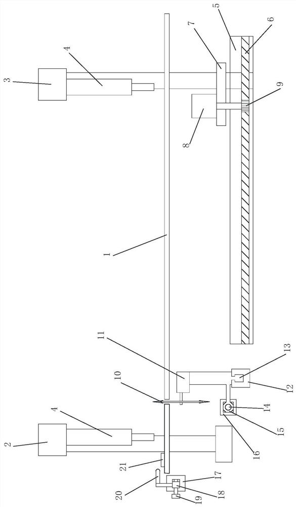
[0027] The specific embodiment of the present invention will be further described below in conjunction with accompanying drawing and specific embodiment:

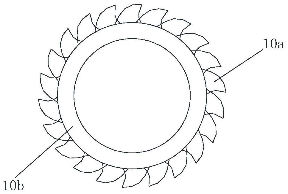
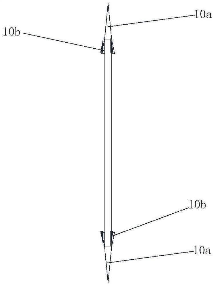
[0028] like Figure 1 to Figure 3 As shown, the aluminum alloy automatic cutting sawing machine includes a controller and a frame. A support platform 1 is set on the frame, a positioning and clamping mechanism 2 is set on one edge of the support platform 1, and a moving clamp is set on the other edge. The clamping mechanism 3, the positioning clamping mechanism 2 and the mobile clamping mechanism 3 are arranged in parallel, the bottom of the mobile clamping mechanism 3 is provided with a clamping and sliding mechanism, and the sliding direction of the clamping and sliding mechanism is clamped with the moving clamping mechanism 3 The fixed line is perpendicular to each other, and a cutting and sliding mechanism is set under the supporting platform 1. The cutting and sliding mechanism is parallel to the positioning and clampi...


PUM


Abstract

The invention provides an automatic aluminum alloy cutting sawing machine and an automatic cutting method. The automatic aluminum alloy cutting sawing machine comprises a controller and a rack, wherein a bearing platform is arranged on the rack; a positioning clamping mechanism is arranged on the edge of one side of the bearing platform; a movable clamping mechanism is arranged at the edge of theother side of the bearing platform; a clamping sliding mechanism is arranged at the bottom of the movable clamping mechanism; a cutting sliding mechanism is arranged below the bearing platform;, a rotary cutting mechanism is connected to the cutting sliding mechanism in a sliding mode; the rotary cutting mechanism comprises a cutting base; a disc cutter is hinged to the cutting base and driven bya cutting motor to be connected; a cutting seam is arranged in the bearing platform; the top of the disc cutter extends out of the cutting seam; a plurality of tooth blades are evenly arranged on theedge of the periphery of the disc cutter; an annular grinding blade is arranged on at least one side face of the disc cutter in a protruding mode and located on the inner periphery of the tooth blades; a measuring guide chute is arranged outside the edge of one side of the bearing platform; a measuring sliding block is clamped in the measuring guide chute in a sliding mode; and a photoelectric sensor is fixedly connected to the measuring sliding block.

Description

technical field [0001] The invention belongs to the technical field of machinery, and relates to a metal plate cutting equipment, in particular to an aluminum alloy automatic cutting sawing machine and an automatic cutting method. Background technique [0002] Aluminum alloy plate or profile parts need to be cut according to the required size. The existing cutting equipment does not have the function of adjusting and fixing plates of different specifications. Therefore, the existing equipment has limitations and cannot adapt to the cutting operation of plates of more specifications. In addition, in the existing equipment, the cutting by the cutter can only be completed from the initial point to the end point. When encountering a plate with a small size, the cutter will continue to cut the plate after cutting the plate, resulting in no-load operation, not only It increases the extra consumption of the power source, wastes time, reduces work efficiency, and affects economic be...

Claims


Application Information

Patent Timeline
Patent Type & Authority Applications(China)
IPC IPC(8): B23D45/06B23D47/00B23D47/08B23D59/00
CPCB23D45/06B23D47/00B23D47/08B23D59/001
Inventor 李媛媛韩双凤于晓张平陈旭亮马玉华刘树涛姜宝
Owner QINGDAO HUANGHAI UNIV
Why Eureka
Try Eureka