Insole punching machine with waste winding function
A technology of waste rewinding and stamping machine, which is applied in the field of stamping machines, can solve the problems of low work efficiency, troublesome operation, inconvenient collection and treatment, etc., and achieve the effect of convenient collection and treatment
- Summary
- Abstract
- Description
- Claims
- Application Information
AI Technical Summary
Problems solved by technology
Method used
Image

Examples
Embodiment 1
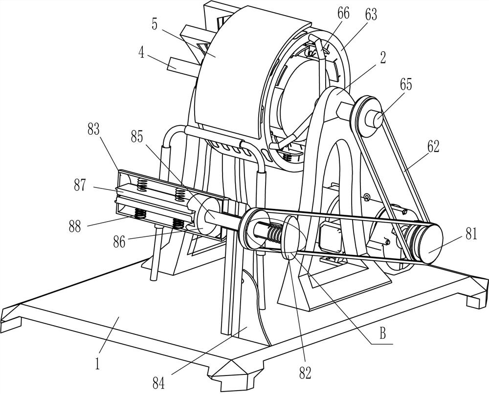
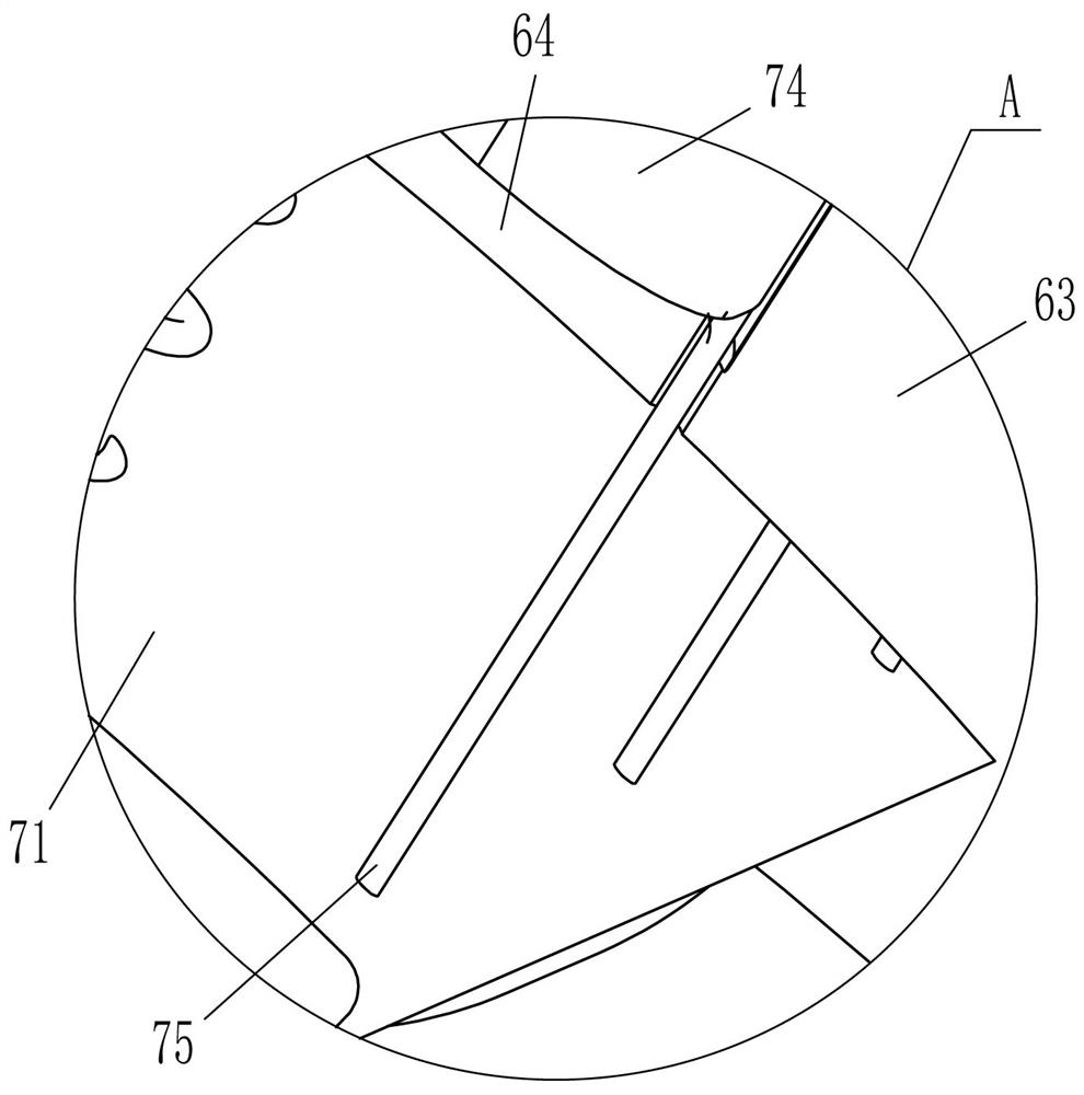
[0023] An insole punching machine with waste rewinding function, such as Figure 1-Figure 4 As shown, it includes a base 1, a support plate 2, a cam column 3, an L-shaped plate 4, an arc-shaped limit plate 5, a driving mechanism 6 and a stamping mechanism 7, and the front and rear parts on the left side of the top of the base 1 are fixedly connected with a support plate 2. A cam column 3 is fixedly connected to the upper part of the rear side of the front support plate 2, and a drive mechanism 6 is provided between the upper part of the rear support plate 2 and the left side of the top of the base 1. The cam column 3 is located in the drive mechanism 6 and is in contact with it. The mechanism 6 is provided with a stamping mechanism 7, three L-shaped plates 4 are fixedly connected to the top right side of the front side support plate 2, and an arc-shaped limiting plate 5 is fixedly connected between the rear ends of the three L-shaped plates 4. The plate 5 cooperates with the d...
Embodiment 2
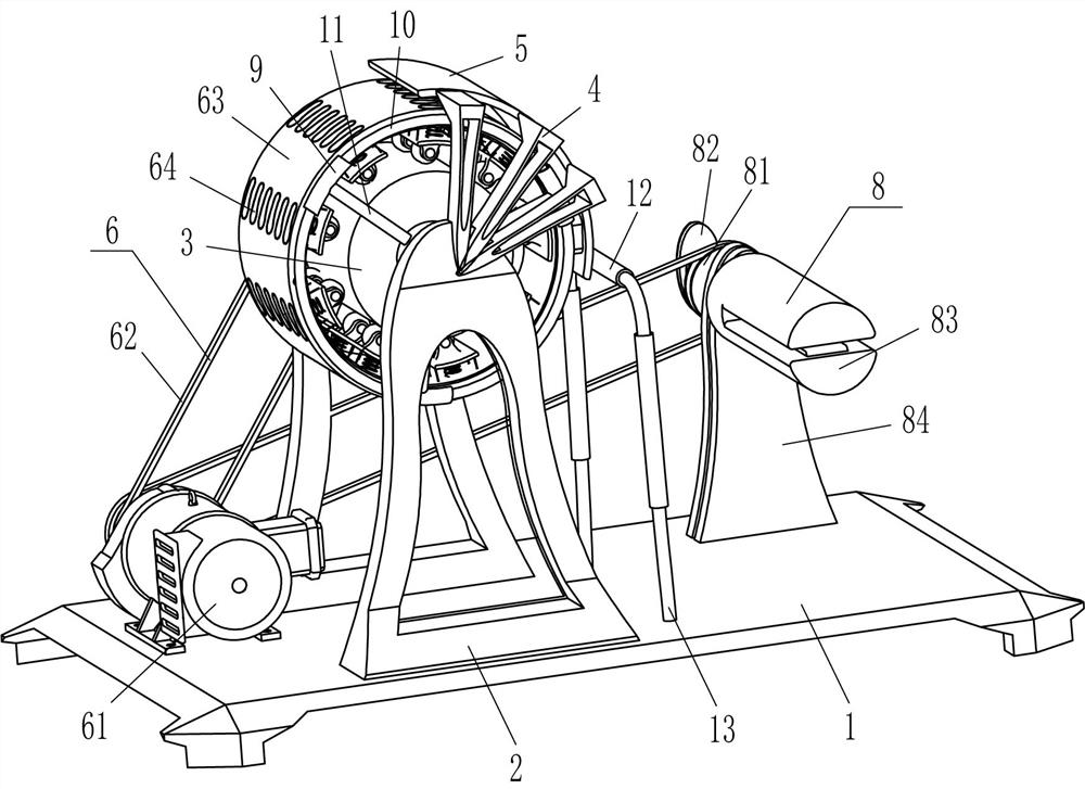
[0030] On the basis of Example 1, such as figure 1 , figure 2 and Figure 5 As shown, a winding mechanism 8 is also included, and the winding mechanism 8 includes a second transmission assembly 81, a pull plate 82, a reel 83, a vertical plate 84, a movable rod 85, a limit block 86, a splint 87, a second spring 88. Guide pipe 89 and the third spring 810. A riser 84 is fixedly connected to the rear part of the right side of the top of the base 1. The middle of the upper part of the riser 84 is connected with a guide pipe 89 in a rotational manner. A second transmission assembly 81 is connected between the output shafts of the motor 61, and a movable rod 85 is slidingly provided in the guide tube 89, and the rear end of the movable rod 85 is fixedly connected with a pull plate 82, and the front side of the pull plate 82 is connected to the guide tube 89 rear end. A third spring 810 is connected between them, the third spring 810 is set on the movable rod 85, the front end of t...
Embodiment 3
[0033] On the basis of embodiment 1 and embodiment 2, such as figure 1 As shown, it also includes a guide sleeve 9, an annular rod 10 and a fixed rod 11, and three fixed rods 11 are affixed to the front side of the cam post 3 at even intervals in the circumferential direction, and the outer end of the fixed rod 11 is affixed with a guide sleeve 9, three An annular rod 10 is slidably arranged between the guide sleeves 9 , and the rear side of the annular rod 10 is fixedly connected with the front side of the annular plate 63 in the circumferential direction.
[0034] Also include guide roller 12 and n-type bar 13, base 1 top right middle is fixedly connected with n-type bar 13, n-type bar 13 upper middle and front and back both sides are all rotatably connected with guide roller 12.
[0035] When the ring plate 63 rotates forward, the ring plate 63 also drives the ring rod 10 to rotate forward, and when the ring plate 63 stops rotating forward, the ring rod 10 also stops rotati...
PUM
 Abstract
Description
Claims
Application Information
 - R&D Engineer
- R&D Manager
- IP Professional
- Industry Leading Data Capabilities
- Powerful AI technology
- Patent DNA Extraction
Browse by: Latest US Patents, China's latest patents, Technical Efficacy Thesaurus, Application Domain, Technology Topic.
© 2024 PatSnap. All rights reserved.Legal|Privacy policy|Modern Slavery Act Transparency Statement|Sitemap