Ultrasonic welding equipment

A technology of ultrasonic welding and equipment, applied in the field of ultrasonic welding equipment, can solve the problems of unstable cycle time, easy misplacement, leakage, manual insertion, etc., to achieve the effect of stable cycle, less error-prone and high efficiency

Pending Publication Date: 2020-12-29
卓研精密工业(苏州)有限公司
View PDF0 Cites 0 Cited by
  • Summary
  • Abstract
  • Description
  • Claims
  • Application Information

AI Technical Summary

Problems solved by technology

The product quality and production efficiency of this kind of operation cannot be guaranteed, and the cost of manpower and machinery is quite high. Manually put in, the cycle time is unstable, and it is easy to be misplaced and missed, which affects the quality and efficiency of ultrasonic welding.

Method used


Image

  • Ultrasonic welding equipment
  • Ultrasonic welding equipment
  • Ultrasonic welding equipment

Examples


Embodiment

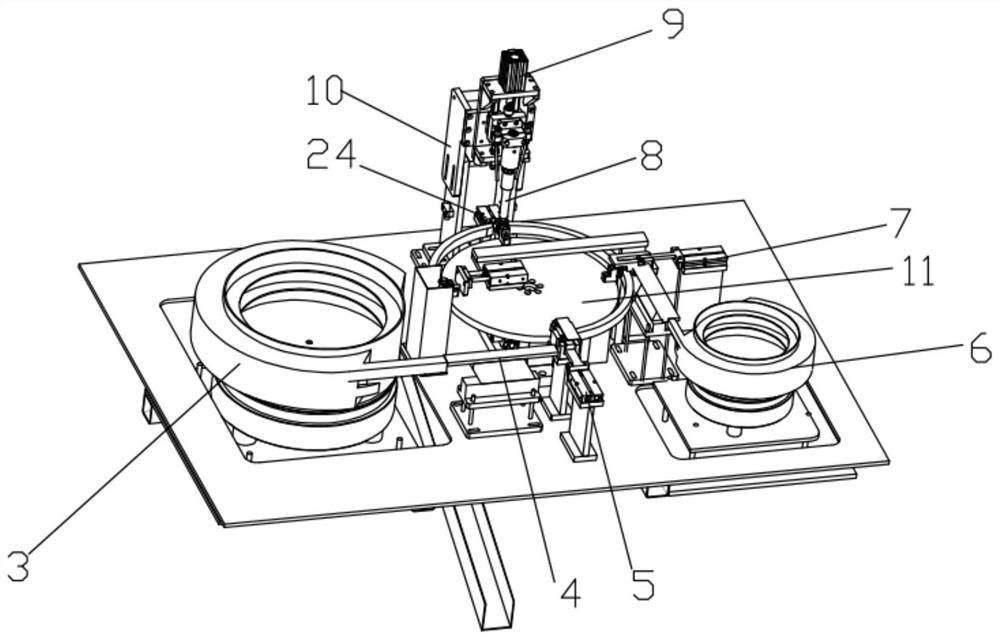
[0021]The following takes the ultrasonic welding of the sheet and the plastic product of Housing as an example to describe the specific implementation and process of the present invention. Unless otherwise specified, all the bodies below correspond to plastic products, and the ligands correspond to sheets. Of course, this welding equipment is not limited to welding such products.

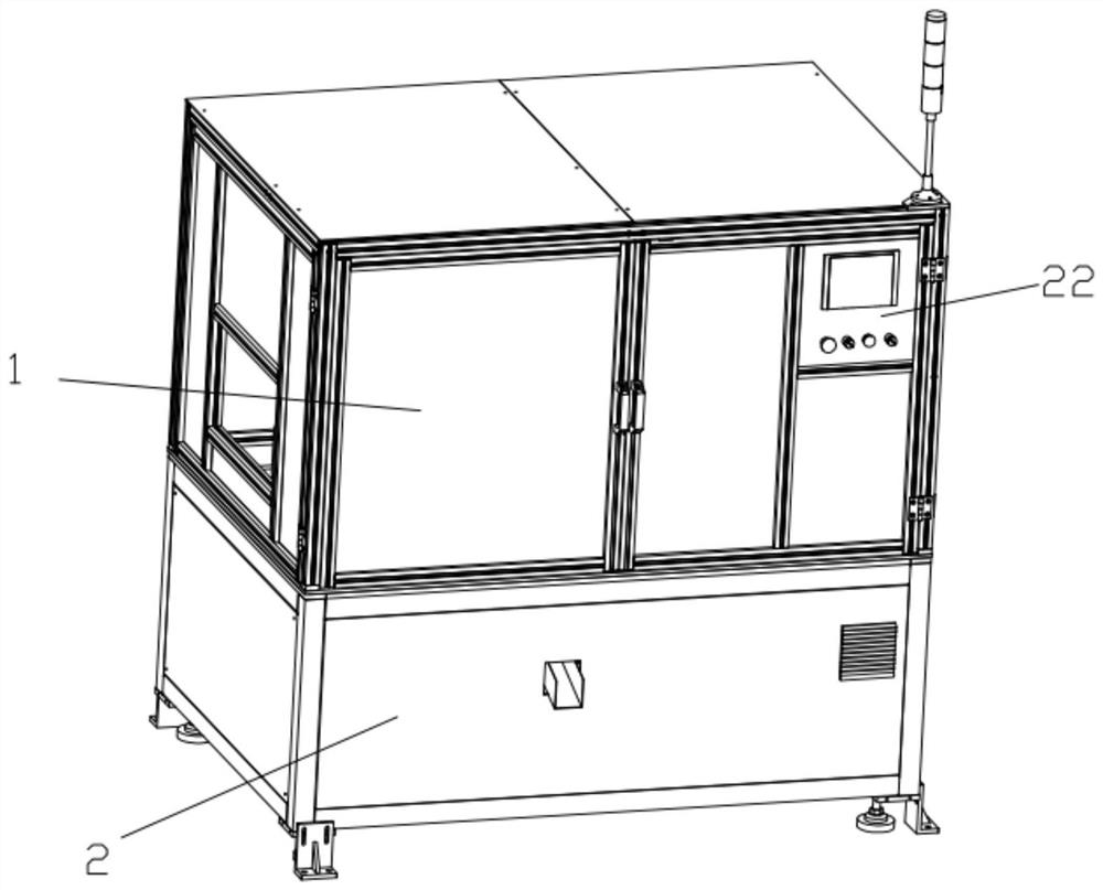
[0022]Such asfigure 1 As shown, the overall shape of the ultrasonic welding equipment invented by the present invention is a box structure, including an upper frame 1 and a lower frame 2. The upper frame 1 is made of aluminum profiles and then installed with a transparent panel. 2 is the lower frame 2 of the square tube, which is enclosed and packaged by square plates.

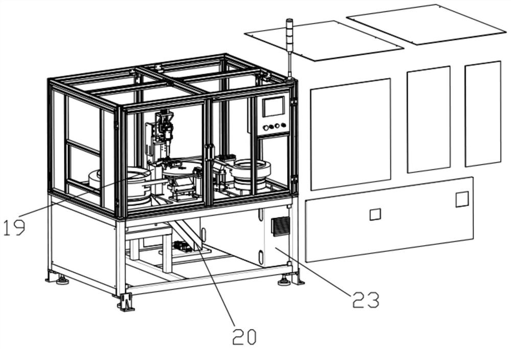
[0023]Combinefigure 1 versusfigure 2 , The upper rack 1 and the lower rack 2 of the ultrasonic equipment are provided with a layer 14 between the upper and lower racks 2 to separate the upper and lower racks 2 into two areas, so that high-power...


PUM


Abstract

The invention relates to the technical field of welding equipment, and particularly discloses ultrasonic welding equipment which comprises a rack. A rotating disc (11) is horizontally arranged in therack, the center of the rotating disc (11) is arranged on an output shaft of a divider (15) in a sleeving manner, and the input end of the divider (15) is connected with a rotating shaft of a motor (16). An ultrasonic welding station, a body feeding station, a ligand feeding station and a discharging station are sequentially arranged on the periphery of the rotary disc (11) in the rotating direction of the rotary disc (11), and a protruding block (12) used for fixing a body is fixed to the position, corresponding to a station working point, of the rotary disc (11). According to the ultrasonicwelding equipment, the whole process of the equipment is controlled by setting the degree through a PLC control system, plastic products and ligands do not need to be placed manually, equipment welding does not need to be started manually, the period is stable, efficiency is high, and errors are not likely to happen.

Description

Technical field[0001]The invention relates to the technical field of welding equipment, and specifically discloses an ultrasonic welding equipment.Background technique[0002]Automation technology is widely used in industry, agriculture, military, scientific research, transportation, commerce, medical care, services and households. The use of automation technology can not only liberate people from heavy physical labor, part of mental labor, and harsh and dangerous working environments, but also expand human organ functions, greatly increase labor productivity, and enhance human ability to understand and transform the world .[0003]In some mechanical processing and production processes, existing factories generally use manual or semi-automatic methods to separate these processes. For example, to weld a sheet and a Housing plastic product together by ultrasonic welding, the current methods are all A single welding equipment and jig are used to manually place the two products on the jig, ...

Claims


Application Information

Patent Timeline
Patent Type & Authority Applications(China)
IPC IPC(8): B29C65/08B29C65/78
CPCB29C65/08B29C65/7858B29C66/80
Inventor 梅翔
Owner 卓研精密工业(苏州)有限公司
Why Eureka
Try Eureka