
Eureka
For R&D, Eureka makes reading and utilizing patents & technical documents easy.
Eureka AIR
Designed for self-driven R&D workflows. Generate viable solutions, solve complex R&D challenges, empower your innovation with AI.

Eureka Materials
Designed for material experts only. Revolutionize your material R&D, from search, analyze, to developing new materials.

TechResearch
Generate reliable direction feasibility study reports for your R&D in just a few steps.

TechSeek
Discover and master advanced knowledge NOW. Basics, ideas, possibilities, all at once.

TechMind
As an expert in R&D Theories, TechMind can generates customized viable solutions instantly.

TechRisk
Analyze your overall solution with one click, know your potential R&D risks in advance.

TechMonitor
Get weekly tech updates, stay abreast of the latest tech innovations and key insights.
High-speed printing press for outer packing material
A technology for outer packaging and printing machines, which is applied to printing machines, rotary printing machines, lithographic rotary printing machines, etc. It can solve the problems of regular shutdown and impact on production efficiency, and achieve the effect of improving sealing and ensuring production efficiency
- Summary
- Abstract
- Description
- Claims
- Application Information
AI Technical Summary
Problems solved by technology
Method used
Image

Examples
Embodiment 1
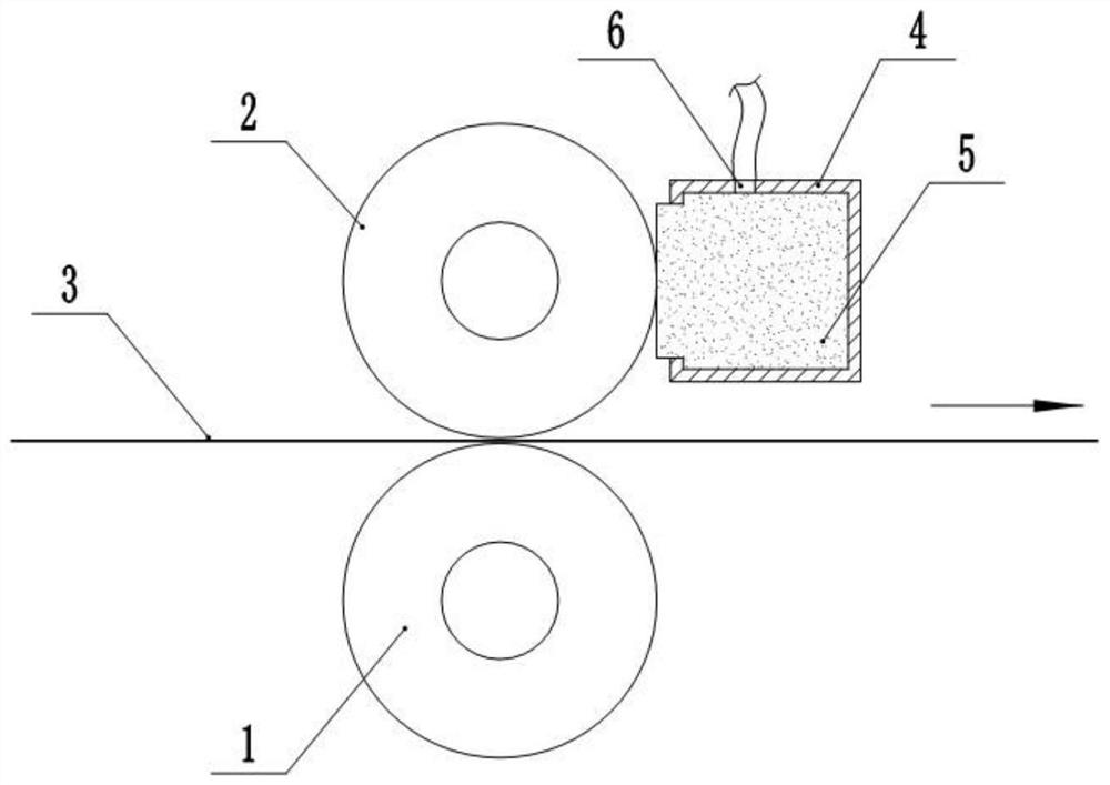
[0035] Basic as attached figure 1 Shown: a high-speed printing machine for outer packaging materials, including a support frame, on which a printing roller 1 and a rubber roller 2 are horizontally rotated and connected, wherein the rubber roller 2 is located above the printing roller 1, and the packaging material 3 to be printed It passes between the rubber roller 2 and the printing roller 1, so the printing roller 1 plays the role of printing, and an ink unit located directly above the rubber roller 2 is also provided on the support frame, and the ink unit is used to transfer ink to the rubber roller 2 Then, the rubber roller 2 prints the ink onto the packaging material 3. The transfer technology of the ink unit is the existing conventional technology, which will not be repeated in this embodiment.
[0036] In this implementation, the packaging material 3 moves to the right, so that the printing roller 1 rotates clockwise, while the rubber roller 2 rotates counterclockwise, a...
Embodiment 2
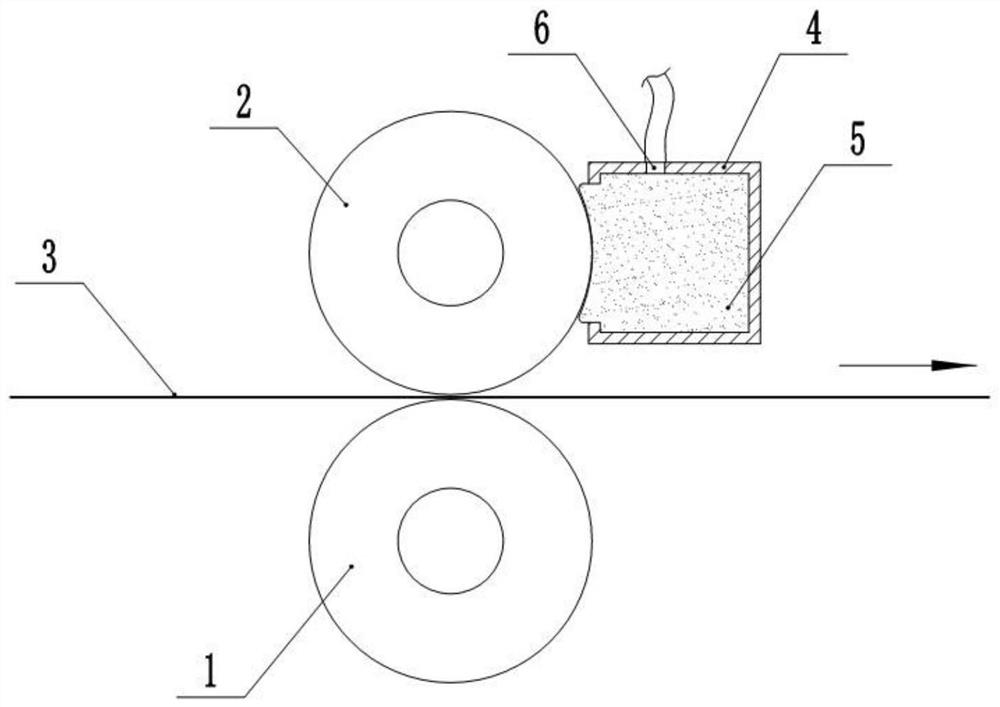
[0039] Basic as attached figure 2 Shown: The difference from Example 1 is that the cross-section of the side of the fixed block 4 close to the rubber roller 2 and the sponge block 5 exposing the adsorption groove is arc-shaped, and the center of the circle is on the same cross-section as the rubber roller 2 The centers of the circles overlap, so that the sponge block 5 and the rubber roller 2 are more fit together, and the adsorption capacity of the ink on the surface of the rubber roller 2 is improved.
Embodiment 3
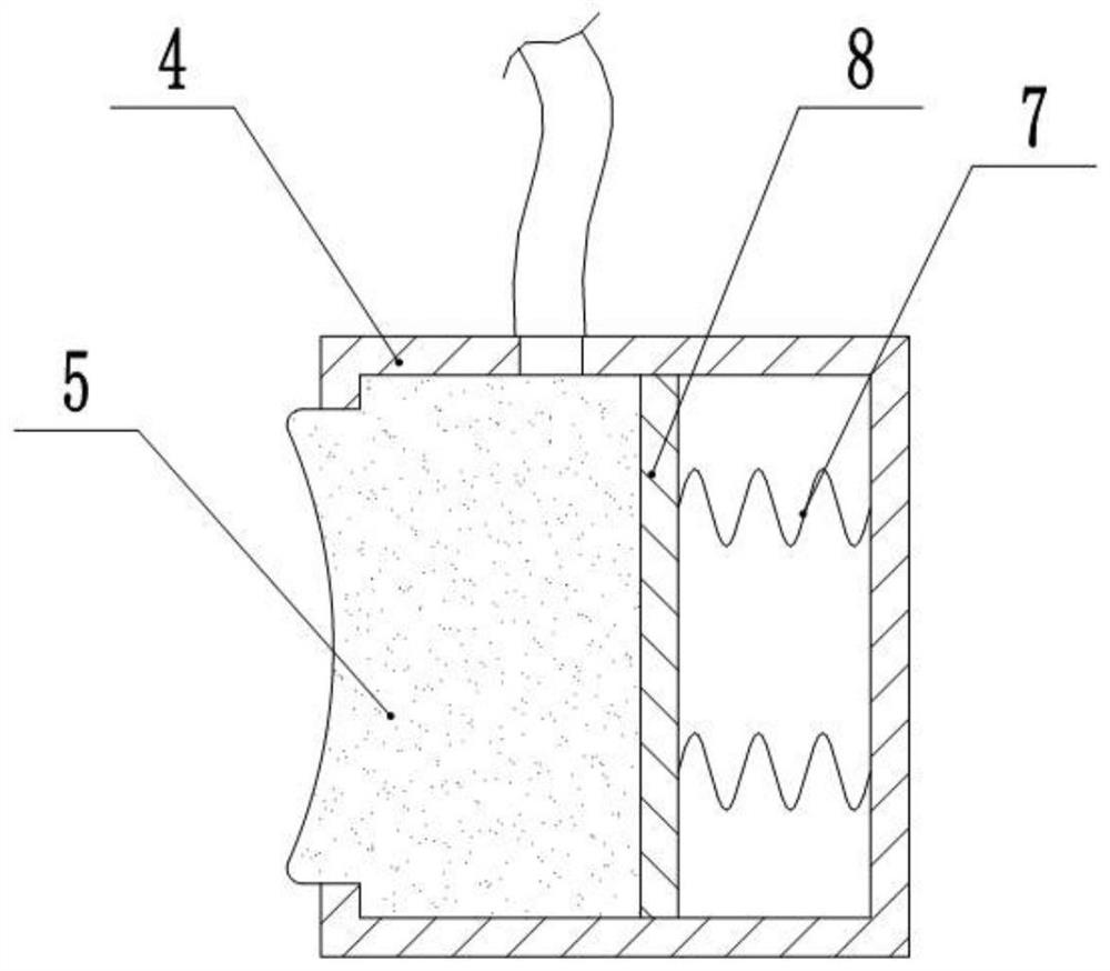
[0041] The difference from Embodiment 2 is that an end cover is provided at one end of the fixed block 4, and the end cover is detachably connected to the fixed block 4, and a sealing ring is provided between the end cover and the fixed block 4, so that the operator can The sponge block 5 can be replaced more conveniently.
PUM
 Abstract
Description
Claims
Application Information
 - R&D Engineer
- R&D Manager
- IP Professional
- Industry Leading Data Capabilities
- Powerful AI technology
- Patent DNA Extraction
Browse by: Latest US Patents, China's latest patents, Technical Efficacy Thesaurus, Application Domain, Technology Topic, Popular Technical Reports.
© 2024 PatSnap. All rights reserved.Legal|Privacy policy|Modern Slavery Act Transparency Statement|Sitemap|About US| Contact US: help@patsnap.com