

Steering device of carton sealer
A technology of steering device and case sealing machine, which is applied to the parts, packaging, transportation and packaging of strapping machinery, which can solve the problems of low sealing efficiency, improve efficiency, reduce the probability of damage, and prolong the time of rotation Effect
- Summary
- Abstract
- Description
- Claims
- Application Information
AI Technical Summary
Problems solved by technology
Method used
Image

Examples
Embodiment 1
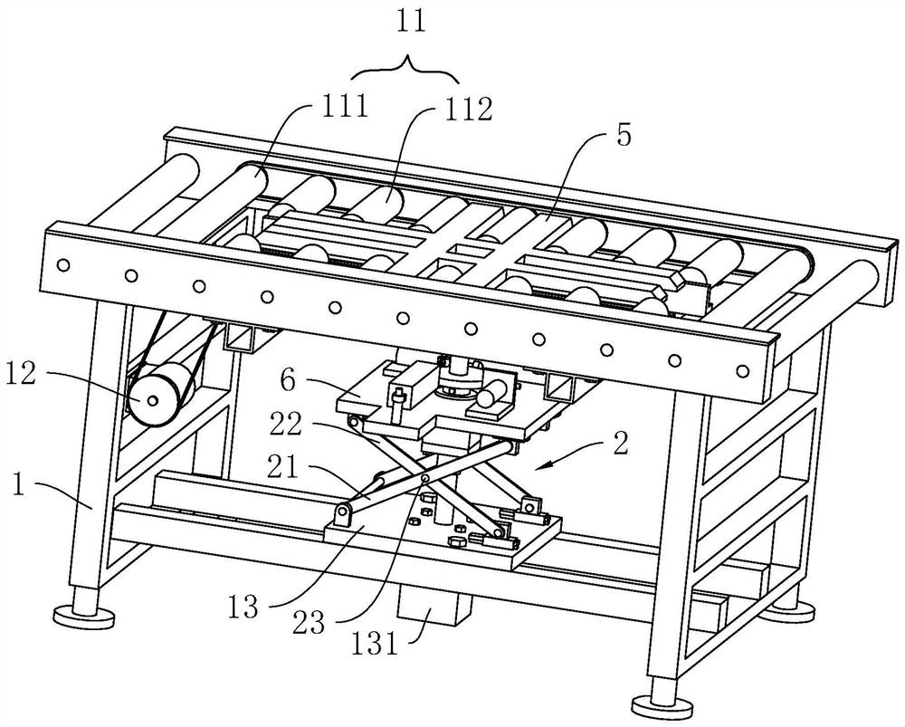
[0045] refer to figure 1 , the steering device includes a frame 1, and the upper end of the frame 1 is rotated to be provided with a horizontal conveying roller 11, and the conveying roller 11 includes a plurality of first conveying rollers 111 and two groups of conveying rollers, and the plurality of first conveying rollers 111 are respectively installed in rotation On the frame 1 and located at both ends of the conveying direction, two sets of conveying rollers are arranged on the frame 1 and between the first conveying rollers 111 at both ends, and the two sets of conveying rollers are arranged at intervals along the vertical and conveying direction, Each set of conveying rollers includes a plurality of second conveying rollers 112 rotatably mounted on the frame 1 at uniform intervals along the conveying direction.
[0046] refer to figure 1 Between the adjacent first conveying rollers 111, between the first conveying rollers 111 and the second conveying rollers 112 are al...
Embodiment 2
[0067] refer to Figure 5 with Image 6 The difference between this embodiment and Embodiment 1 is that in order to improve the steering accuracy, a centering assembly 7 is provided on the frame 1 and at one end of the entry plate 5, and the centering assembly 7 includes two pull claws 71. The third driving member 72. The third driving member 72 includes a fourth cylinder 721 / fourth hydraulic cylinder, two sprockets 722, and a chain 723. In this embodiment, the fourth cylinder 721 is used.
[0068] refer to Image 6 , on the frame 1 and at one end of the entry plate 5 is fixedly provided with a slide bar 16, the slide bar 16 is located below the first conveying roller 111, the length direction of the slide bar 16 is parallel to the length direction of the conveying roller 11, two pull claws 71 is slidingly installed on the slide rod 16, and the pull claw 71 extends out of the transmission plane where the first conveying roller 111 is located; the fourth cylinder 721 is fixed...
Embodiment 3
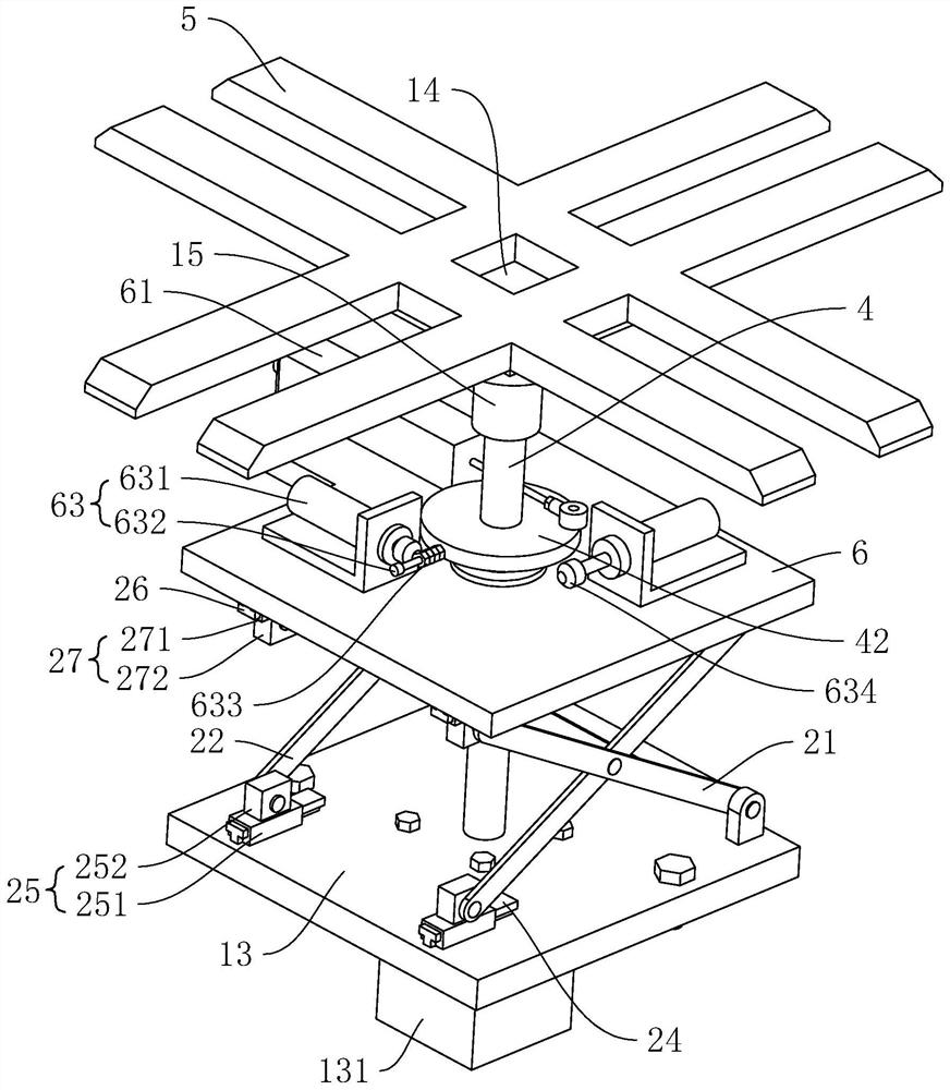
[0073] refer to Figure 7 , The difference between this embodiment and Embodiment 1 / Embodiment 2 is: the second driving member includes a gear 81, a third cylinder 82 / a third hydraulic cylinder, and a rack 83, and the third cylinder 82 is adopted in this embodiment, The gear 81 is a ring gear and is integrally coaxially sleeved on the connection plate 42; two fixed pieces 64 are installed at intervals on the lifting plate 6, and the fixed pieces 64 are L-shaped. On the plate 6, the other side of the fixed piece 64 is vertical, and the side where the two fixed pieces 64 are connected to the lifting plate 6 is located at the back side of the vertical side. Both ends of the cylinder block of the third cylinder 82 are also connected and fixed on the vertical sides of the two fixing pieces 64 by first bolts 641 .
[0074] refer to Figure 7 , a slideway 65 is fixedly arranged on the lifting plate 6, and a slider 66 is slidably arranged on the slideway 65. The rack 83 is installed...
PUM
 Abstract
Description
Claims
Application Information