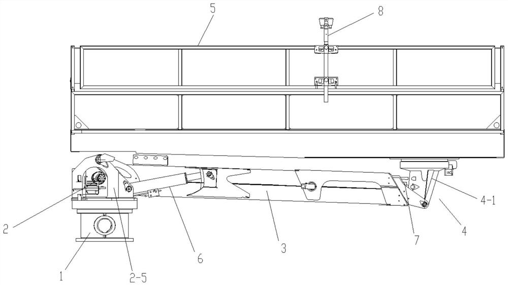
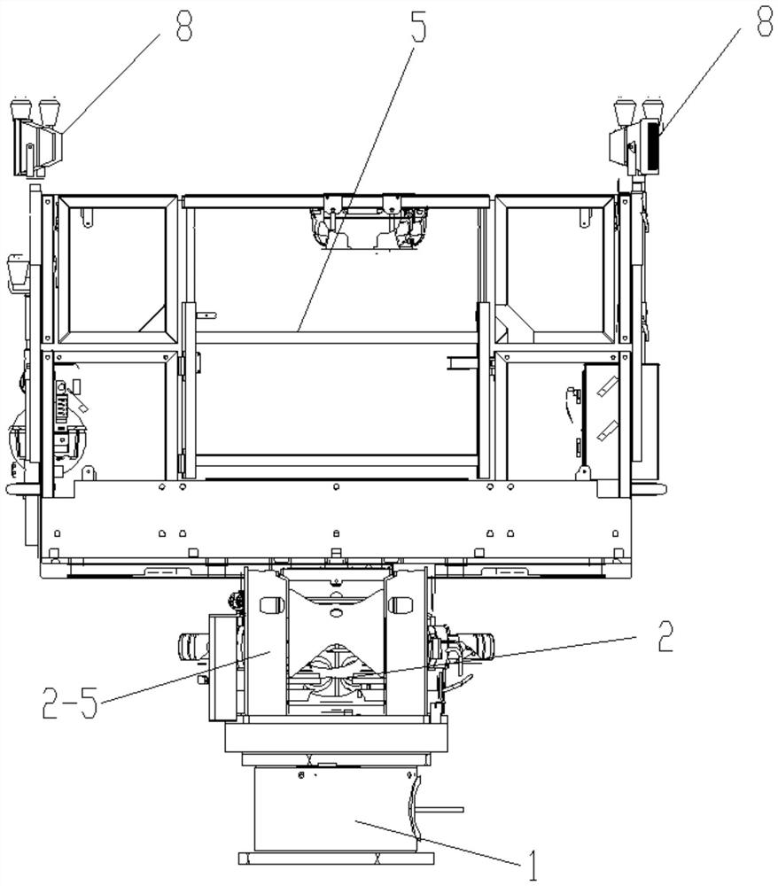
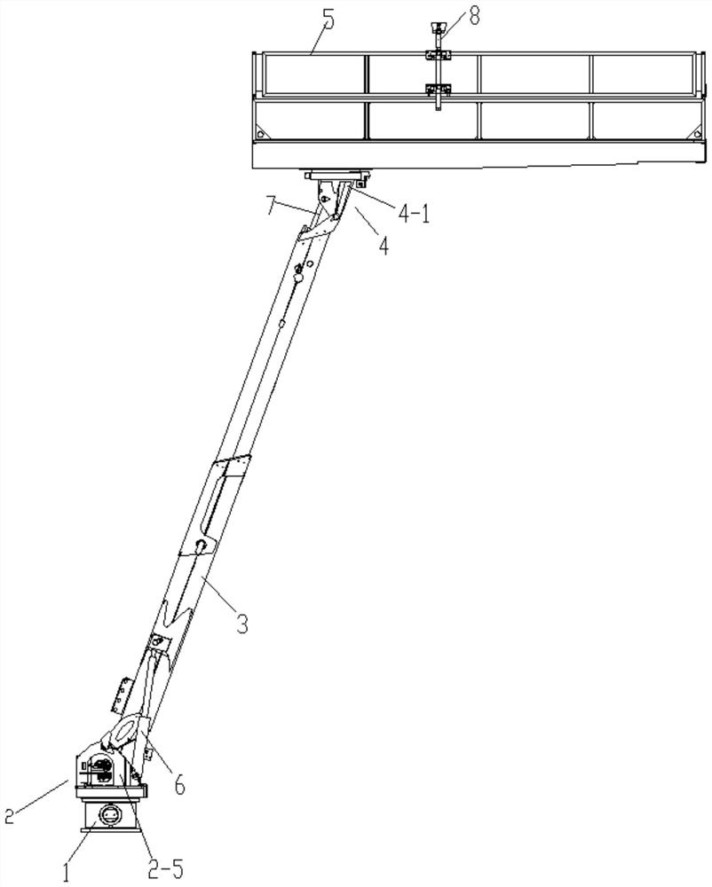
[0024]Attached belowFigure 1-7 An embodiment of the present invention is described so as to clearly and completely describe the technical solution. Obviously, the described embodiments are only a part of the embodiments of the present invention, rather than all the embodiments.
[0025]In the description of the present invention, it should be understood that the terms "upper", "lower", "front", "rear", "left", "right", "top", "bottom", "inner", " The orientation or positional relationship indicated by "outside" is based on the orientation or positional relationship shown in the drawings, which is only for the convenience of describing the present invention and simplifying the description, and does not indicate or imply that the device or element referred to must have a specific orientation. The specific orientation structure and operation, therefore, cannot be understood as a limitation of the present invention.
[0026]Straight arm double-rotation overhaul work platform mechanism, such asFigure 1-3As shown, it includes a base 1 fixedly connected to the frame. Specifically, the base 1 is fixed to the top of the frame by bolts. The base 1 is fixed with a primary turning device 2 which is fixed to the upper end. The secondary slewing device 4 with a working platform 5 is connected by a luffing telescopic device 3. The operating platform 5 is provided with a wire lifting device 8, and the primary slewing device 2 is provided with one end of the luffing telescopic device 3 articulated It is also used to adjust the luffing cylinder 6 of the luffing and telescopic device 3, and the other end of the luffing and telescopic device 3 is provided with a leveling cylinder 7 articulated with the secondary slewing device 4 and used for adjusting the angle of the working platform 5; in the above structure , On the basis of 2360° continuous rotation of the first-stage slewing device, the 360° continuous rotation of the second-stage slewing device 4 is integrated to provide conditions for the flexible rotation adjustment of the working platform 5, and the luffing cylinder 6 is set to realize the luffing and stretching The adjustment of the pitching action of the device 3 and the setting of the leveling cylinder 7 are used to adjust the angle of the work platform 6 so as to ensure that the work platform 6 is always level and provide safe and reliable work adjustment for the operators.
[0027]Such asFigure 4 As shown, the first-stage slewing device 2 includes a slewing support 2-1, a first-stage hydraulic motor 2-2, a reducer 2-3, and a driving gear 2-4. The two ends of the horizontal center line below the slewing support 2-1 Both are equipped with a first-level hydraulic motor 2-2 and a reducer 2-3. The lower end of the outer ring of the slewing support 2-1 is fixed with a mounting plate 2-6 and a reducer 2-3 input on the mounting plate 2-6. The shaft is fixedly connected with the output shaft of the first-stage hydraulic motor 2-2 installed on the base 1, and the drive gear 2-4 on the output shaft of the reducer 2-3 meshes with the inner gear ring of the slewing support 2-1, A support seat 2-5 is fixed on the inner gear ring of the slewing support 2-1, the end of the piston rod of the luffing cylinder 6 is hinged to the outside of one end of the luffing telescopic device 3, and one end of the luffing telescopic device 3 and the luffing cylinder The cylinders of 6 are all hinged to the support base 2-5; in the above technical solution, the rotation of the support base 2-5 is driven by the first-stage hydraulic motor 2-2 and the drive gear 2-4 is driven by the reducer 2-3 to rotate. The 360° continuous rotation of the luffing and retracting device 3, the above structure can also be realized by the slewing support 2-1 of the outer gear ring and the inner ring structure;
[0028]Such asFigure 6 As shown, the secondary slewing device 4 includes a secondary slewing seat 4-1, a secondary hydraulic motor 4-2, a worm wheel 4-3, and a worm 4-4. The worm wheel 4-3 is fixed to the bottom of one end of the work platform 5. And the worm 4-4 installed at the upper end of the secondary slewing seat 4-1 meshes with the worm wheel 4-3, the end of the worm 4-4 is fixedly connected with the output shaft of the secondary hydraulic motor 4-2, and the secondary rotary The lower end of the seat 4-1 is hinged with the other end of the luffing and telescopic device 3, one end of the leveling cylinder 7 is hinged to the other end of the luffing and telescopic device 3, and the end of the piston rod of the leveling cylinder 7 is hinged to the secondary revolving base 4 1 Outside; after the secondary hydraulic motor 4-2 drives the worm 4-4 to rotate, the worm 4-4 drives the worm wheel 4-3 to rotate, so as to realize the 360° continuous rotation of the work platform 5; in the above structure, not only the worm wheel 4 can be used -3 The transmission structure of the worm 4-4 can also adopt the bevel gear transmission structure;
[0029]Such asFigure 5 As shown, the luffing and telescopic device 3 includes a basic arm 3-1, a telescopic arm 3-2, and a telescopic cylinder 3-3. Both the basic arm 3-1 and the telescopic arm 3-2 adopt a box-shaped structure. It adopts a polygonal structure, a circular structure, and an elliptical structure. One end of the basic arm 3-1 is hinged with the primary turning device 2 and the other end of the basic arm 3-1 is sleeved with one end of the telescopic arm 3-2. Two telescopic cylinders 3-3 are installed in -1. The piston rod of the telescopic cylinder 3-3 is connected with the pin on the inner wall of the other end of the telescopic arm 3-2, and the telescopic cylinder 3-3 controls the expansion and contraction. The expansion and contraction of the arm 3-2 is that the end of the piston rod of the luffing cylinder 6 which is located on both sides of the basic arm 3-1 and is hinged on the primary turning device 2 is hinged with the basic arm 3-1, and the telescopic arm 3-2 Two leveling cylinders 7 are installed symmetrically at the other end, and the end of the piston rod of the leveling cylinder 7 is articulated with the secondary slewing device 4; in the above technical solution, the overall pitching action of the luffing and telescopic device 3 is through the luffing cylinder 6 piston rod In the above technical solution, the overall length of the luffing telescopic device 3 is mainly driven by the telescopic cylinder 3-3 piston rod to drive the telescopic arm 3-2 to expand and contract. The change in the length of the luffing telescopic device 3 finally realizes the adjustment of the height of the work platform 5; the luffing and telescopic device 3 used in this structure is a primary telescopic structure, and a secondary or multi-level telescopic structure can also be used to realize the work platform 5 Height adjustment: In this structure, the telescopic cylinder 3-3 is a built-in structure, and an external structure can also be used to achieve the above functions.
[0030]Such asFigure 7 As shown, the line lifting device 8 includes a height adjustment rod 8-1, a fixing seat 8-2 and a line claw 8-3. The height adjustment rod 8-1 is located outside the railing of the work platform 5 and the height adjustment rod 8-1 is mounted on the railing of the work platform 5 in a height-adjustable manner through a plurality of fixing bases 8-2, the wire-drawing claw 8-3 is fixed to the upper end of the height adjusting rod 8-1; specifically, the fixing base 8- 2 Consists of a U-shaped groove plate 8-4 and a fixing sleeve 8-5 fixed on the middle of the outer plate surface of the U-shaped groove plate 8-4. The fixing sleeve 8-5 is sleeved on the height adjustment rod 8-1 and passed through threads The handwheel locking bolt 8-6 installed on the fixing sleeve 8-5 tightens and fixes the height adjustment rod 8-1, and the railing crossbar of the work platform 5 is located in the U-shaped groove of the U-shaped groove plate 8-4 And the U-shaped groove plate 8-4 is fixed to the railing crossbar of the work platform 5 through the fastening bolts fixedly connected to the lower end of the U-shaped groove plate 8-4, and the outer ends of the fastening bolts are fixed to facilitate the rotation operation Horizontal fastening handles 8-7; In the above technical solution, a wire lifting device 8 for conducting wires is integrated on the work platform 5. During operation, the wire lifting claws 8-3 in the wire lifting device 8 realize the lifting of the wires. The function of the line and the line, so as to facilitate the maintenance of the catenary, the height and position of the line lifting device 8 can be adjusted, and the adjustment is flexible and convenient, the operability is good, and the work platform space is increased. , The carrying capacity is increased, the number of workers and equipment that can be accommodated increases, and maintenance operations are more utilized.
[0031]In this structure, the rotation angles of the first-level slewing device 2 and the second-level slewing device of the straight-arm double-swing overhaul work platform mechanism include any angle value within 0~360°, and the rotation angle can be limited by mechanical rotation limit, or The rotation angle can be limited by means of limit switches and control logic.
[0032]Under the operating conditions of the technical scheme, the accuracy of the fixed-point parking of the vehicle is reduced, and the flexibility of the action of the operating platform can be fully utilized to compensate and adjust the position of the operating platform, thereby effectively improving the operating efficiency.
[0033]The above-mentioned embodiments are only preferred embodiments of the present invention and are not used to limit the scope of implementation of the present invention. Therefore, all equivalent changes made with the content of the claims of the present invention shall be included in the scope of the claims of the present invention. .