Reinforced concrete frame joint HDC wire winding reinforcing device and construction method thereof

A reinforced concrete and reinforcement device technology, applied in building maintenance, construction, building construction, etc., can solve the unfavorable changes in the failure form of the reinforced structure, the inconvenient application of primer and structural adhesive, and the reinforcement of the core area of ​​the joint and the end of the column and other issues, to achieve the effect of earthquake resistance, simple construction, and increased bearing capacity

Pending Publication Date: 2020-12-29
FUZHOU UNIV
View PDF0 Cites 3 Cited by
  • Summary
  • Abstract
  • Description
  • Claims
  • Application Information

AI Technical Summary

Problems solved by technology

However, the above-mentioned combined reinforcement method has many disadvantages. For example, after the broken concrete in the node area has many edges and corners, it is easy to split the pasted fiber cloth, and it is not convenient to apply primer and structural adhesive; Unfavorable; conventional prestressed steel tendon reinforcement usually can only produce constraints near the corners of components and the core area of ​​joints, which is consistent with the force mechanism of fiber cloth or stirrups wrapped frame columns, and the stirrups will

Method used


Image

  • Reinforced concrete frame joint HDC wire winding reinforcing device and construction method thereof
  • Reinforced concrete frame joint HDC wire winding reinforcing device and construction method thereof
  • Reinforced concrete frame joint HDC wire winding reinforcing device and construction method thereof

Examples


Embodiment Construction

[0028] In order to make the above-mentioned features and advantages of the present invention more comprehensible, the following specific embodiments are described in detail with reference to the accompanying drawings.

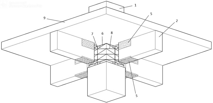
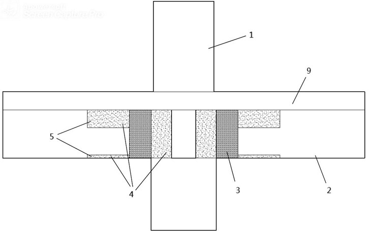
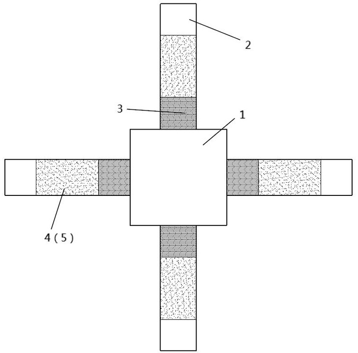
[0029] Such as Figure 1~5 As shown, the reinforced concrete frame node HDC wire-wound reinforcement device includes a vertical frame column 1 and a horizontally extending frame beam 2 around it, and the reinforcement area of ​​the reinforcement device includes a connected full-height replacement area 3 and a partial replacement area. Zone 4, the full-height replacement area is formed by chiseling through the frame beam itself and the contact end of the frame column, and the partial replacement area is formed by chiseling inward from the outer peripheral surface of the frame column to the core area of ​​the internal node of the frame column, and the core area of ​​the node is exposed Vertical steel bars 7 are fixedly connected to the midpoints of the stirrups 6...


PUM


Abstract

The invention relates to a reinforced concrete frame joint HDC wire winding reinforcing device and a construction method thereof. The reinforced concrete frame joint HDC wire winding reinforcing device comprises a vertical frame column and a frame beam extending horizontally on the peripheral side of the vertical frame column. A reinforcing area of the reinforcing device comprises a full-height replacement area and a partial replacement area which communicate with each other, and the full-height replacement area is formed by chiseling and penetrating the contact end of the frame beam and the frame column. The partial replacement area is formed by chiseling inwards from the peripheral surface of the frame column to a joint core area in the frame column, vertical steel bars are fixedly connected to connecting lines of midpoints of exposed stirrups of the joint core area, the steel bars are connected into a whole in a winding mode through cold-drawn steel wires, and the full-height replacement area and the partial replacement area are reinforced through HDC spraying, smearing, filling and reinforcing. By arranging the multiple sections of replacement areas, weakening beam ends are reinforced, the number of plastic hinges of the beam end under the action of an earthquake is increased, the redundancy of joint damage is improved, concrete in the core area can be restrained more efficiently by adopting the cold-drawn steel wires and steel bars for wire winding, the hooping effect of the core area is improved, and the restraining effect on the concrete is improved.

Description

technical field [0001] The invention relates to a reinforced concrete frame joint HDC wire-wound reinforcement device and a construction method thereof. Background technique [0002] In the reinforced concrete frame structure, the connection node between the frame column and the frame beam is a crucial part of the whole structure, which is mainly composed of the core area of ​​the node where the frame column and beam intersect and the connected column end and beam end. In the overall frame structure, it plays the role of transferring load and distributing internal force. Node design is the key line of defense against earthquake fortification. According to my country's "Code for Seismic Design of Buildings" (GB 50011-2010), under the action of strong earthquakes, the normal failure form of reasonably designed nodes is that the plastic hinge area at the beam end first appears fine vertical towards the crack. With the continuous input of seismic energy, the concrete in the com...

Claims


Application Information

Patent Timeline
IPC IPC(8): E04G23/02
CPCE04G23/0218E04G2023/0251
Inventor 方圣恩黄培徐
Owner FUZHOU UNIV
Why Eureka
Try Eureka