Gas relay calibration device

A technology of calibration device and relay, which is applied in the direction of circuit breaker testing, etc., can solve the problem of polluting the calibration table and achieve an intuitive demonstration effect

Pending Publication Date: 2020-12-29
ELECTRIC POWER RES INST OF STATE GRID ANHUI ELECTRIC POWER
View PDF0 Cites 1 Cited by
  • Summary
  • Abstract
  • Description
  • Claims
  • Application Information

AI Technical Summary

Problems solved by technology

[0004] In order to solve the problem in the background technology that after the calibration of the gas relay is removed, the rema

Method used


Image

  • Gas relay calibration device
  • Gas relay calibration device

Examples


Embodiment 1

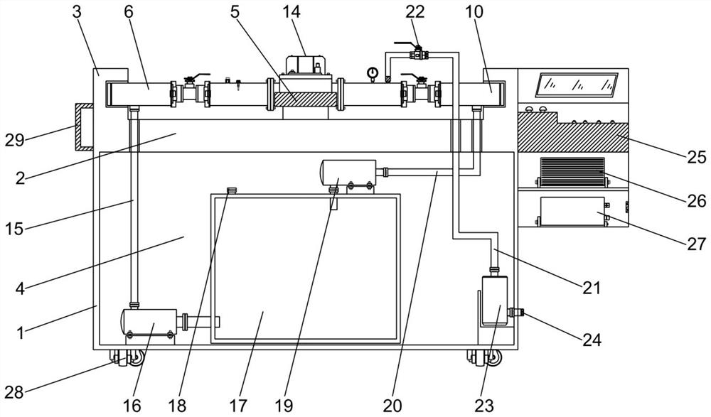
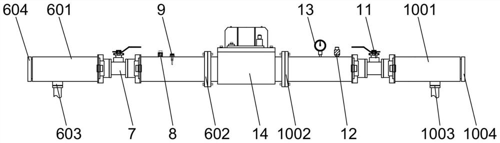
[0024] Embodiment 1: Buchholz relay calibration device, such as figure 1 As shown, it includes a box body 1, the top of the box body 1 is fixedly provided with a workbench 2, the left and right ends of the workbench 2 are fixedly provided with vertical fixing seats 3, and the middle part of the workbench 2 is provided with a place for placing the gas relay 14. The deck 5 includes a two-jaw chuck and a cylinder providing power for the two-jaw chuck, and the two-jaw chuck is fixed on the workbench. Such as figure 1 with figure 2 As shown, the left side of the card seat 5 is provided with an oil delivery test pipeline I6, and the oil delivery test pipeline I6 includes a hard transparent tube I601 that is transparent on the left and right, and the right end of the hard transparent tube I601 is fixedly connected with a flange piece I602. The left end of the transparent tube I601 is provided with a screw-connected plug I604, and the fixed seat 3 on the left side is provided with ...

Embodiment 2

[0031] Embodiment 2: Buchholz relay calibration device, the oil tank 17 is set as a fully sealed box structure, further reducing the possibility of oil leakage of the device. Other structures are the same as in Example 1.


PUM


Abstract

The invention provides a gas relay calibration device, and solves the problem that residual oil in test pipelines flows out to pollute a calibration table after a gas relay is dismounted after being calibrated. After the gas relay calibration device is adopted to calibrate the gas relay, a regulating valve II is fully opened, an oil well pump is started, oil in an oil transportation test pipelineI and an oil transportation test pipeline II is quickly pumped, a regulating valve III is opened after the oil well pump is closed, an air pump is started, gas is injected into the oil transportationtest pipelines, pressurization is performed, the residual oil in the oil transportation test pipeline I, the oil transportation test pipeline II and the gas relay is extruded into an oil return pipe,and the cleaning degree of the residual oil is observed in real time through a hard transparent pipe I and a hard transparent pipe II in the process; and after cleaning is completed, the regulating valve III is closed, an exhaust port is opened, and the exhaust port is closed after pressure relief. By adopting the gas relay calibration device, no residual oil exists in the two oil transportation test pipelines basically.

Description

technical field [0001] The invention relates to the technical field of electric power safety production test, in particular to a calibration device for a gas relay. Background technique [0002] Gas relay (also known as gas relay) is a protective device used in transformers. It is installed in the pipeline between the oil conservator and the oil tank of the transformer. Make the contact of the gas relay act, connect the designated control circuit, and send out a signal alarm in time (light gas) or start the protection element to automatically cut off the transformer (heavy gas). Light gas is mainly reflected when the gas decomposed by oil rises into the gas relay during operation or minor failure, the air pressure makes the oil level drop, the opening cup of the relay falls with the oil level, and the light gas reed contact is connected to send a signal. When there is too much gas, the gas can be released by the gas nozzle of the gas relay. Heavy gas is mainly reflected in...

Claims


Application Information

Patent Timeline
IPC IPC(8): G01R31/327
CPCG01R31/327
Inventor 李远松高博丁津津汪玉郑国强徐斌李圆智王丽君孙辉张峰汪勋婷何开元
Owner ELECTRIC POWER RES INST OF STATE GRID ANHUI ELECTRIC POWER
Why Eureka
Try Eureka