
System and method for generating equipment ledger hierarchical tree from EMS substation graph model

A technology for generating equipment and substations, applied in the transmission system, information technology support system, electrical components, etc., can solve the problem of restricting the reliability of power transmission and transformation, the sharing of accounts between stations and lines, and the impact of dispatching automation master station systems and GIS Issues such as the development of platform collaborative applications and the inability to realize transmission, transformation, and distribution topology connectivity

Pending Publication Date: 2020-12-29
CHINA SOUTHERN POWER GRID COMPANY +1
View PDF4 Cites 1 Cited by
  • Summary
  • Abstract
  • Description
  • Claims
  • Application Information

AI Technical Summary

Problems solved by technology

[0002] Due to the historical reasons for the construction of dispatch automation and enterprise management information systems, the master station system of dispatch automation at all levels maintains the substation map model, and the GIS platform maintains the complete power transmission and distribution map model data, and no effective map has been established between the two. The model interaction and sharing mechanism cannot realize the connection of transmission, transformation, and distribution topologies, which affects the development of collaborative applications between the master station system of dispatching automation and the GIS platform, and restricts the reliability of power transmission and transformation, the relationship between stations and lines, and the relationship between dispatching automation and " Applications such as ledger sharing among 6+1” systems directly affect the effective integration of enterprise industrialization and informatization

Method used


Image

  • System and method for generating equipment ledger hierarchical tree from EMS substation graph model
  • System and method for generating equipment ledger hierarchical tree from EMS substation graph model
  • System and method for generating equipment ledger hierarchical tree from EMS substation graph model

Examples


Embodiment

[0028] The embodiments of the present invention will be described in detail below in conjunction with the accompanying drawings. Apparently, the described embodiments are only some of the embodiments of the present invention, not all of them.

[0029] In describing the present invention, it should be understood that the terms "upper", "lower", "front", "rear", "left", "right", "top", "bottom", "inner", " The orientation or position or sequence relationship indicated by "outer", "first", "second", etc. are based on the orientation or position or sequence relationship shown in the drawings, and are only for the convenience of describing the present invention and simplifying the description, rather than indicating or It should not be construed as limiting the invention by implying that a referenced device or element must have a particular orientation, be constructed, and operate in a particular orientation.

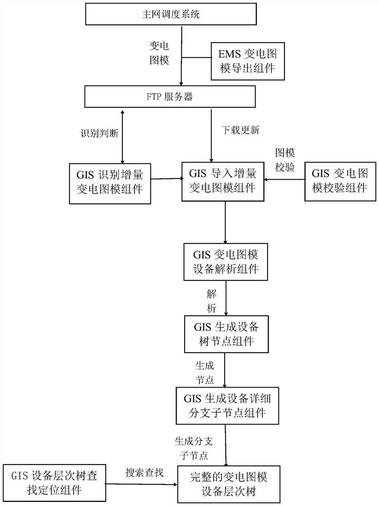
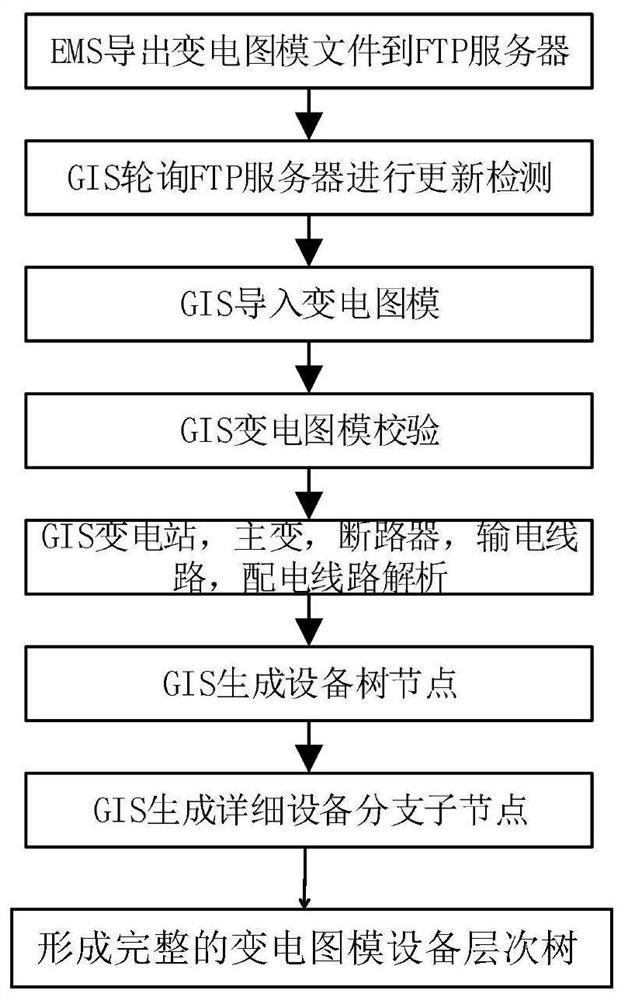
[0030] See attached figure 1 , a hierarchical tree system for generati...


PUM


Abstract

The invention discloses a system for generating an equipment ledger hierarchical tree from an EMS transformer substation graph model. The system comprises an EMS terminal, an FTP server and a GIS terminal. The EMS terminal comprises: an EMS power transformation diagram model exporting assembly which is used for exporting a transformer substation diagram model in an EMS system to the FTP server; the GIS terminal comprises a GIS identification incremental power transformation diagram module assembly, a GIS import incremental power transformation diagram module assembly, a GIS power transformation diagram module verification assembly, a GIS power transformation diagram module equipment analysis assembly, a GIS generation equipment tree node assembly, a GIS generation equipment detailed branchsub-node assembly and a GIS equipment hierarchical tree searching and positioning assembly. According to the method, the equipment ledger hierarchical tree is generated from the EMS transformer substation graph model, substation graph model fusion of an EMS system and an informatization system is achieved, and the supporting effect of data in the system on services is brought into full play for the basis and preconditions of service application.

Description

technical field [0001] The invention relates to the technical field of power grid dispatching systems, in particular to a system and method for generating a hierarchical tree of equipment ledgers from an EMS substation diagram. Background technique [0002] Due to the historical reasons for the construction of dispatch automation and enterprise management information systems, the master station system of dispatch automation at all levels maintains the substation map model, and the GIS platform maintains the complete power transmission and distribution map model data, and no effective map has been established between the two. The model interaction and sharing mechanism cannot realize the connection of transmission, transformation, and distribution topologies, which affects the development of collaborative applications between the master station system of dispatching automation and the GIS platform, and restricts the reliability of power transmission and transformation, the rel...

Claims


Application Information

Patent Timeline
IPC IPC(8): G06Q10/10G06Q50/06H04L29/08
CPCG06Q10/103G06Q50/06H04L67/06Y04S10/50
Inventor 吴争荣朱文邓大为方文崇夏伟李志坚张昆王义昌周志烽顾慧杰
Owner CHINA SOUTHERN POWER GRID COMPANY
Learn More