
Inverter

An inverter device and inverter technology, applied in the inverter field, can solve the problems of low heat dissipation capacity and heat dissipation efficiency of the inverter device, and achieve the effects of improving heat transfer and heat dissipation efficiency, enhancing heat transfer, and improving heat dissipation efficiency

Active Publication Date: 2022-02-18
厦门科华数能科技有限公司
View PDF7 Cites 0 Cited by
  • Summary
  • Abstract
  • Description
  • Claims
  • Application Information

AI Technical Summary

Problems solved by technology

Both the boost circuit and the inverter circuit are equipped with power inductors and power switches (such as IGBTs). Most of the heat generated by the inverter device during operation comes from the above two devices, although there are many A heat dissipation structure is used to dissipate heat from the above-mentioned devices, but it is still difficult to solve the defects of low heat dissipation capacity and heat dissipation efficiency of existing inverter devices

Method used


Image

  • Inverter
  • Inverter
  • Inverter

Examples


Embodiment Construction

[0041] The following will clearly and completely describe the technical solutions in the embodiments of the present invention with reference to the drawings in the embodiments of the present invention. Obviously, the described embodiments are preferred embodiments of the invention and should not be seen as excluding other embodiments. Based on the embodiments of the present invention, all other embodiments obtained by persons of ordinary skill in the art without creative efforts fall within the protection scope of the present invention.

[0042] In the claims, description and above-mentioned drawings of the present invention, unless otherwise clearly defined, the terms "first", "second" or "third" are used to distinguish different objects, not for Describe a specific order.

[0043] In the claims, specification and above-mentioned drawings of the present invention, unless otherwise clearly defined, for orientation words, such as using the terms "center", "transverse", "longit...


PUM


Abstract

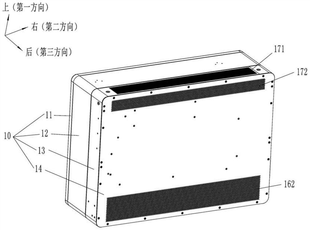
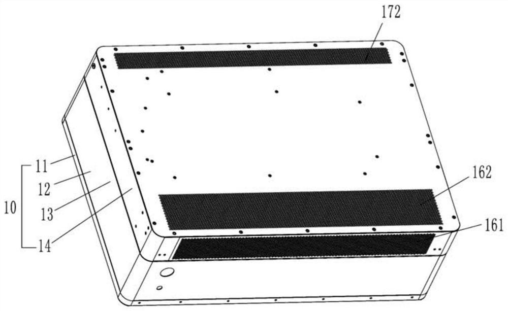
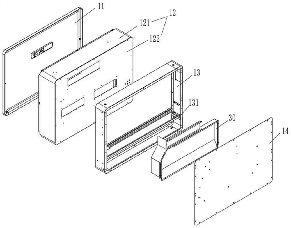
The invention discloses an inverter device, comprising: a shell, a power module, a heat dissipation structure and an air guide structure; the power module includes a power switch tube; the heat dissipation structure includes a fan and a power switch tube radiator; the power switch tube The radiator has a plurality of heat dissipation teeth; the air guide structure includes a first air guide plate, the first air guide plate is at least partially covered by the power switch tube radiator and adjacent to the heat dissipation of the power switch tube radiator The tooth crest setting. The inverter device of the present invention concentrates the air supply airflow to the heat sink of the power switch tube to dissipate heat through the air guide structure, and can guide the airflow to the tooth root of the heat dissipation tooth, so that the airflow velocity at the tooth root is faster, and due to the The temperature difference between the temperature and the air supply air flow is larger, which can effectively enhance the heat transfer at the root of the tooth, and improve the heat transfer and heat dissipation efficiency.

Description

technical field [0001] The invention relates to the field of inverter technology, in particular to an inverter device. Background technique [0002] An inverter device with an inverter circuit, such as a photovoltaic inverter and an uninterruptible power supply, generally includes a boost circuit and an inverter circuit coupled to each other. Both the boost circuit and the inverter circuit are equipped with power inductors and power switches (such as IGBTs). Most of the heat generated by the inverter device during operation comes from the above two devices, although there are many A heat dissipation structure is used to dissipate heat from the above-mentioned devices, but it is still difficult to solve the defects of low heat dissipation capacity and heat dissipation efficiency of the existing inverter device. Contents of the invention [0003] The purpose of the present invention is to overcome at least one defect or problem existing in the background technology, and pro...

Claims


Application Information

Patent Timeline
Patent Type & Authority Patents(China)
IPC IPC(8): H02M7/00H05K7/20
CPCH02M7/003H05K7/20909Y02E10/56
Inventor 叶南志倪泽联林智鹏钟联胜
Owner 厦门科华数能科技有限公司
Learn More