A Rotationally Excited Friction-Piezoelectric Composite Generator

A piezoelectric composite, generator technology, applied in the direction of friction generators, generators/motors, piezoelectric effect/electrostrictive or magnetostrictive motors, etc., can solve the friction and wear between friction pairs of sliding friction generators, Vibration frequency and rotating body speed adaptability are low, power generation capacity and energy density per unit volume are low, etc., to achieve the effect of strong speed adaptability, simple structure and excitation process, and avoid surface friction and wear

Active Publication Date: 2021-10-01
ZHEJIANG NORMAL UNIVERSITY
View PDF9 Cites 0 Cited by
  • Summary
  • Abstract
  • Description
  • Claims
  • Application Information

AI Technical Summary

Problems solved by technology

From the perspective of practical application, various types of generators currently proposed still face many technical bottlenecks. The common problems are summarized as follows: ① low power generation capacity and energy density per unit volume; Low adaptability to flow velocity, vibration frequency and rotating body speed, ③low reliability, such as piezoelectric ceramics are easily damaged due to excessive environmental vibration intensity, and sliding friction generators are easy to fail due to friction and wear between friction pairs. ④There is electromagnetic interference , such as electromagnetic generators, nonlinear piezoelectric and friction generators based on magnetic coupling auxiliary excitation, there is a certain magnetic field when they work
Of course, it is still difficult to solve all the above-mentioned problems in the same generator
The common feature of pure piezoelectric generators and friction generators is that they have no electromagnetic interference, so they are more suitable for wireless sensor monitoring systems, and their respective power generation capabilities, reliability and environmental adaptability need to be further improved

Method used


Image

  • A Rotationally Excited Friction-Piezoelectric Composite Generator
  • A Rotationally Excited Friction-Piezoelectric Composite Generator
  • A Rotationally Excited Friction-Piezoelectric Composite Generator

Examples


Embodiment Construction

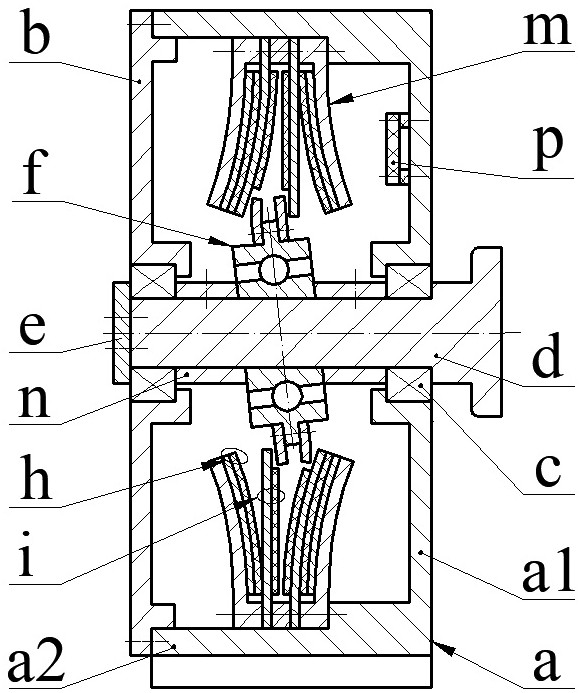
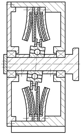
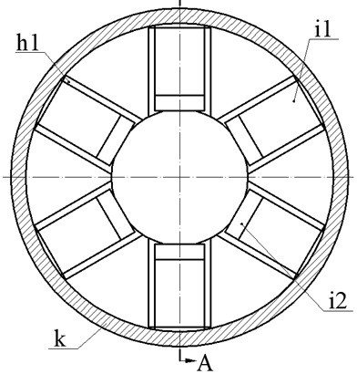
[0021] The composite generator proposed by the present invention mainly includes a casing a, a bearing c, an end cover b, a rotating shaft d, a shaft sleeve n, an exciter f equipped with a plectrum j, a bracket m, a composite film h, and a piezoelectric vibrator i and circuit board p. The end cover b is installed on the end of the casing a2 of the casing a through screws, the rotating shaft d is installed on the end cover b and the bottom a1 of the casing a through the baffle e and the bearing c, and the bearing c is connected through the baffle e and the rotating shaft d The shaft shoulder is positioned, and the block e is installed on the end of the rotating shaft d without the shoulder through a screw.

[0022] The swing ring f2 of the exciter f is set on the fixed ring f1 through the rolling body f3. The rolling body f3 is a ball or a cylinder. The angle Q between the fixed ring axis x1 and the swing ring axis x2 in the same plane is called the shaft inclination angle. The ...


PUM


Abstract

The invention relates to a rotationally excited friction-piezoelectric composite generator, which belongs to the technical field of new energy sources. The end cover is installed at the end of the cylinder, and the rotating shaft is installed on the end cover and the bottom of the shell; the swing ring of the exciter is set on the fixed ring, and there is an axial inclination between the fixed ring and the axis of the swing ring, and a dial ring is arranged on the outer edge of the swing ring. Both sides of the ring are equipped with paddles, the fixed ring is installed on the rotating shaft and rotates with the rotating shaft; the two brackets and the spacer ring are installed on the inner side of the shell, the bracket is composed of a ring plate and a guard plate, and the convex surface of the guard plate is provided with Composite film composed of friction layer and electrode layer; a piezoelectric vibrator is crimped between the ring plate of the bracket and the spacer ring, the substrate of the piezoelectric vibrator is installed close to the friction layer, and the piezoelectric vibrator and the composite film constitute a friction pair; The paddle on the side is located between two axially adjacent piezoelectric vibrators; when the shaft rotates, the paddle forces the piezoelectric vibrator to reciprocally bend and deform, and repeatedly contacts and separates from the composite film, the substrate of the piezoelectric vibrator and the piezoelectric vibrator The piezoelectric power generation end is formed between the sheets, and the friction power generation end is formed between the substrate and the composite film.

Description

technical field [0001] The invention belongs to the technical field of new energy and energy recovery, and in particular relates to a rotationally excited friction-piezoelectric composite generator for collecting wind energy, water flow and kinetic energy of a rotating body. Background technique [0002] In recent years, real-time health sensing monitoring technology for high-rise buildings, bridges, large and high-speed rotating machinery has been widely used. In addition, the monitoring of river water quality pollution, flood prevention and early warning, and air pollution has been highly valued by relevant state departments. Domestic experts and scholars have successively proposed corresponding monitoring methods and means, such as water quality monitoring technology for river water pollution, flood control Monitoring technologies such as rainfall, water level, and river water velocity for natural disasters such as landslides and mudslides. At the same time, in order to ...

Claims


Application Information

Patent Timeline
Patent Type & Authority Patents(China)
IPC IPC(8): H02N2/18H02N1/04
CPCH02N1/04H02N2/185H02N2/186
Inventor 张忠华叶林峰柴君凌翟仕杰陈文涛余义勇阚君武曾平
Owner ZHEJIANG NORMAL UNIVERSITY
Why Eureka
Try Eureka