Improving arc fault detection by using frequency hopping technology

A technology of arc fault and frequency hopping sequence, which is applied in the direction of fault location, circuit device, electrical components, etc., to achieve the effect of reducing harmful detection and tripping

Pending Publication Date: 2020-12-29
SCHNEIDER ELECTRIC USA INC
View PDF0 Cites 0 Cited by
  • Summary
  • Abstract
  • Description
  • Claims
  • Application Information

AI Technical Summary

Problems solved by technology

However, this detection method only allows detection of a small window of the arcing signal, for example, a narrow frequency region
Furthermore, such frequency regions m

Method used


Image

  • Improving arc fault detection by using frequency hopping technology
  • Improving arc fault detection by using frequency hopping technology
  • Improving arc fault detection by using frequency hopping technology

Examples


Embodiment Construction

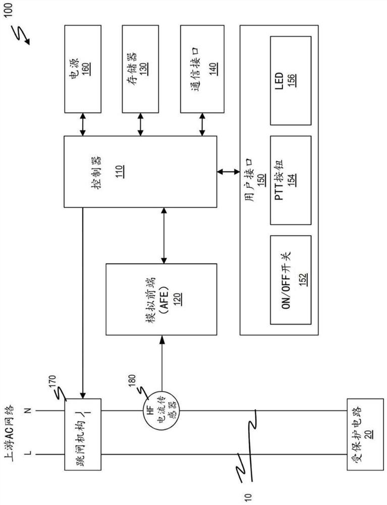
[0029] figure 1 A block diagram of an example circuit breaker 100 with an arc fault detection system for monitoring high frequency signals on an AC power line 10 (eg, a 50 / 60 Hz power line) of a protected circuit 20 is shown. The circuit breaker 100 includes a controller 110, an analog front end (AFE) 120 that receives signals from a high frequency (HF) sensor 180, a memory 130, a communications / transmission medium to communicate with a remote or other device or system Interface 140 , user interface 150 , power supply 160 to power the components of circuit breaker 100 , and trip mechanism 170 to interrupt power on power line 10 upstream of protected circuit 20 . The user interface 150 may include an ON / OFF switch 152 (e.g., a handle), a push-to-test (PTT) button for testing the circuit breaker, and a button for indicating the status of the circuit breaker (e.g., on, off, One or more LEDs or other indicators for reset, trip, etc.) or other circuit breaker information. The HF ...


PUM


Abstract

An arc fault detection system samples a high frequency signal on a power line sequentially at different frequency regions according to a frequency hopping sequence, wherein the sampling is repeated anumber of times over a predefined period. The different frequency regions include at least one region with a carrier for power line communication on the power line and at least one region without a carrier for power line communication on the power line. The system obtains energy measurements for each frequency region based on the sampled signals, computes an energy level for each frequency regionbased on the measurements for each region, and assigns a binary value to each region according to the corresponding energy level. The binary value represents a presence or absence of signal content inthe frequency region. The system determines a presence or absence of an arc fault based on the binary values for the frequency regions.

Description

technical field [0001] The present disclosure relates to a method and system for improving arc fault detection, and more particularly, to a method and system for improving interoperability of arc fault detection and power line communications (PLC) in branch circuits . Background technique [0002] Power line communication (PLC) devices may be used in buildings, such as residences (eg, houses, condominiums, apartments, etc.), to enable data communication across power system infrastructure (eg, power lines of branch circuits). PLC devices communicate in the high frequency range, for example, in the unregulated range from 2MHz to 30MHz and up to 86MHz (see, for example, HomePlug Avx and HomePlug GreenPhy). The power line communication protocol used by the PLC device may include, for example, IEEE 1901, IEEE P1901.2, HomePlug GP / AV / AV2 / 1.0, G.hn or G.hnem. When PLC devices are used together with arc fault circuit interrupter (AFCI) devices in buildings or other structures, the...

Claims


Application Information

Patent Timeline
IPC IPC(8): G01R31/08H02H3/50
CPCH02H1/0015H02H1/0092H04B1/713H02H3/33
Inventor A.贾库皮P.A.雷德G.斯科特J.贝尔施密特M.拉尤尔H.雷西格尔C.瓦西里
Owner SCHNEIDER ELECTRIC USA INC
Why Eureka
Try Eureka