
Guide device for blood sampling pen

A lancet and lancet technology, applied in the field of medical devices, can solve problems such as poor effect, and achieve the effects of alleviating pain, preventing the occurrence of secondary puncture, and preventing secondary puncture.

Pending Publication Date: 2021-01-01
周元军
View PDF2 Cites 0 Cited by
  • Summary
  • Abstract
  • Description
  • Claims
  • Application Information

AI Technical Summary

Problems solved by technology

[0006] The technical problem to be solved by the present invention: the purpose of the present invention is to provide a guiding device for the blood collection pen, thereby reducing the shaking when the blood collection needle is punctured, and preventing secondary punctures at the same time, and solving the inability of the existing medical blood collection device The problem of balance and poor effect

Method used


Image

  • Guide device for blood sampling pen
  • Guide device for blood sampling pen
  • Guide device for blood sampling pen

Examples


Embodiment 1

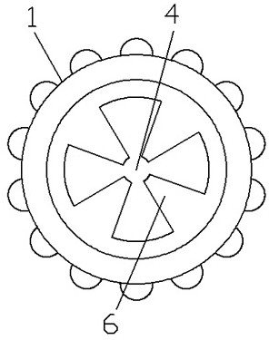
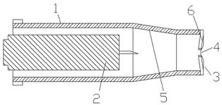
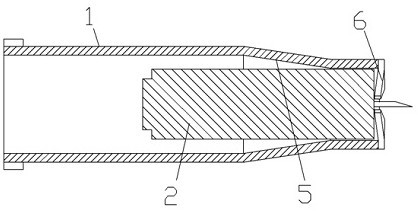
[0027] Such as Figure 1~4 A guiding device for a blood collection pen is shown, which includes a blood collection needle 2 for puncturing blood collection and a sleeve 1 that cooperates with the blood collection needle 2 and is used to limit the ejection direction and distance of the blood collection needle 2 .

[0028] The blood collection needle 2 is formed by connecting a needle body and a needle handle, and the needle tip of the needle body head protrudes from the front end of the needle handle in a ready-to-fire state. The outside of the head of the cannula 1 is provided with a blood collection end face 3, and the blood collection end face 3 is provided with a pinhole 4, such as image 3 As shown, the needle point passes through the needle hole 4 and punctures under the shooting puncture state.

[0029] The above structure is the prior art for the blood collection device. In order to reduce the shaking when the blood collection needle is punctured and prevent the occur...

Embodiment 2

[0041] See attached Figure 6~9 As shown, the guiding device for a blood collection pen includes a blood collection needle 2 for puncturing blood collection and a sleeve 1 that cooperates with the blood collection needle 2 and is used to limit the ejection direction and distance of the blood collection needle 2 .

[0042] Embodiment 2 differs from Embodiment 1 in that: a dividing groove 8 is provided on the wall of the casing 1 corresponding between the two adjacent elastic claws 6, and the root of the elastic claw 6 is thinner than that of Embodiment 1. This can change the elastic capacity of the elastic claw 6 . Since the wall of the casing 1 corresponding to the root of the elastic claw 6 is provided with a dividing groove 8, it has elastic deformation ability in the inner and outer directions, see Figure 9Arrow on the side of the head of cannula 1 shown in . This elastic force is beneficial to the guiding and buffering of the lancet 2 during shooting.

[0043] Below fo...


PUM


Abstract

The invention discloses a guide device for a blood sampling pen, and belongs to the field of medical instruments. According to the technical scheme, in order to reduce shaking of a blood taking needleduring puncture and prevent secondary puncture, at least two elastic claws are arranged at the head of a sleeve, the elastic claws are distributed in the circumferential direction of the head of thesleeve at intervals, and meanwhile a guide slope is arranged on the inner side face of the head of the sleeve. In the ejection process of the blood taking needle, the ejection direction of the blood taking needle is guided through the guide slope, then the buffering effect is achieved through the elasticity of the elastic claws when the blood taking needle is impacted, the needle tip can be effectively prevented from shaking through the combination of the structural design, the secondary puncture phenomenon can be effectively prevented, and extra parts do not need to be added. The guide deviceis reasonable in design and ingenious in conception, can effectively relieve the pain when the needle body penetrates into the skin of a human body, and can also weaken the impact force generated when the blood taking needle is ejected and the sound generated by impact.

Description

technical field [0001] The invention belongs to the field of medical equipment, and in particular relates to a guiding device for a blood collection pen. Background technique [0002] Medical blood collection device is a kind of medical blood collection device, which is widely used in various medical institutions and diabetic patients. There are various structural forms of medical blood collection devices, but they can generally be divided into two categories: blood collection pens and disposable blood collection devices. The blood collection pen is a pen-type medical blood collection device. Usually, the blood collection pen is used together with the blood collection needle. The blood collection pen is equivalent to a pistol and can be reused many times, while the blood collection needle is equivalent to a bullet. For safety, it can only be used once. The disposable blood collection device comes with a blood collection needle and an ejection mechanism, and is popular among...

Claims


Application Information

Patent Timeline
Patent Type & Authority Applications(China)
IPC IPC(8): A61B5/151
CPCA61B5/15113A61B5/15115
Inventor 周元军
Owner 周元军
Learn More