
Cuvette group cleaning device

A technology for cleaning devices and cuvettes, which is applied in the field of cuvette cleaning, can solve problems such as complex structure, poor practicability, collision between cuvettes and cleaning devices, and achieve cross-contamination, good cleaning effect, and sewage discharge effect Good results

Pending Publication Date: 2021-01-01
柳州市柳铁中心医院
View PDF1 Cites 2 Cited by
  • Summary
  • Abstract
  • Description
  • Claims
  • Application Information

AI Technical Summary

Problems solved by technology

In the prior art, there are already some devices for cleaning cuvettes, which can be used to clean the cuvette group under certain circumstances, such as the cuvettes of a fully automatic biochemical analyzer disclosed in the Chinese utility model whose application number is CN200520094114.3. Cleaning device, but these existing cleaning devices cannot be adjusted because the cleaning needle seat is fixed, resulting in a cleaning device that can only be used for one type of cuvette set, which is extremely weak in versatility and not strong in practicability; The existing cleaning devices for cuvette sets are equipped with many moving mechanisms such as electric motors and electric push rods, and the structure is complex. During the cleaning process, each link needs to move the cuvettes relative to the cleaning device, which not only takes time If the input of the cleaning program is wrong, it is easy to cause the cuvette to collide with the cleaning device, resulting in damage to the cuvette and the cleaning device; The stain itself is not easy to remove. After brushing one cuvette and then brushing another cuvette, it is easy to cause cross-contamination, resulting in residual stains, etc.

Method used


Image

  • Cuvette group cleaning device
  • Cuvette group cleaning device
  • Cuvette group cleaning device

Examples


Embodiment Construction

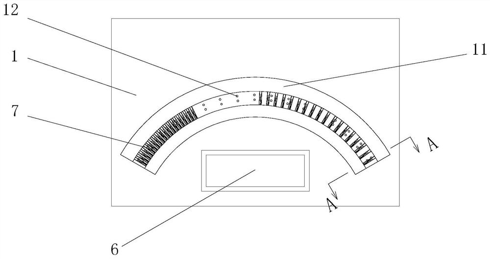
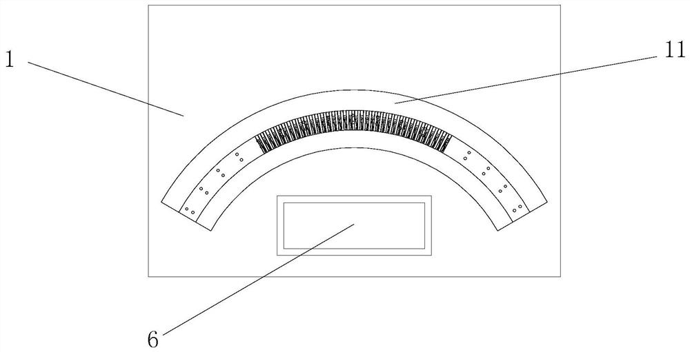
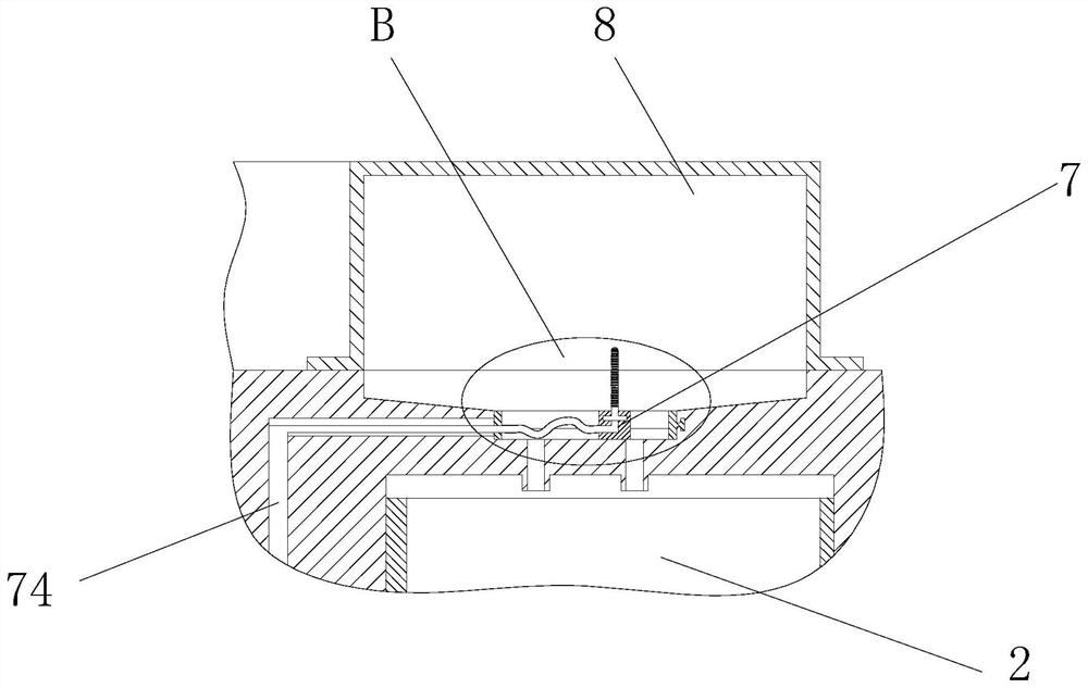
[0044] The technical solutions in the embodiments of the present invention will be clearly and completely described below in conjunction with the accompanying drawings in the embodiments of the present invention. Obviously, the described embodiments are only some of the embodiments of the present invention, not all of them. The accompanying drawings are for illustrative purposes only, and represent only schematic diagrams, rather than actual drawings, and should not be construed as limitations on this patent. In order to better illustrate the specific implementation of the present invention, some parts of the accompanying drawings will be omitted or enlarged Or reduced, does not represent the size of the actual product. For those skilled in the art, it is understandable that some known structures, components and their descriptions in the drawings may be omitted. Based on the embodiments of the present invention, those skilled in the art All other embodiments obtained under the ...


PUM


Abstract

The invention relates to the technical field of cuvette cleaning, and particularly relates to a cuvette group cleaning device. The cuvette group cleaning device comprises a machine box, a sewage box,a water purifying box, a cleaning box, a controller, an operation panel and a cleaning mechanism, wherein a groove with a fan-shaped horizontal projection surface is formed in the upper surface of themachine box, and a plurality of through holes are formed in the groove; the sewage box is arranged below the groove, the operation panel is arranged at the upper end of the machine box, and the sewage box, the water purifying box, the cleaning box and the controller are arranged in the machine box; and the cleaning mechanism comprises a plurality of sliding frames, a plurality of sliding blocks,a plurality of hoses, a main pipeline, a plurality of electric control valves, a plurality of nozzles, a water purifying pump and a cleaning pump. According to the cuvette group cleaning device, in the process of cleaning cuvettes, the cuvettes do not need to be moved, the cuvette group cleaning device can be suitable for cleaning most cuvette groups used by analyzers, the universality is high, the cuvettes on the cuvette groups do not need to be taken down during cleaning, the operation is simple and convenient, the cleaning effect is good, and the sewage discharging effect is good.

Description

technical field [0001] The invention relates to the technical field of cuvette cleaning, in particular to a cuvette group cleaning device. Background technique [0002] A cuvette is an instrument used for spectral analysis. It is mainly a quartz cuvette fired from quartz powder, and there are also micro, semi-micro, fluorescent and other cuvettes. In the field of analysis and testing, when it is necessary to use colorimetry to analyze samples, it is necessary to use cuvettes and analyzers. The cuvettes used are basically set up in groups. The cuvette set is a fan-shaped structure. Each cuvette set is composed of multiple cuvettes. Different types of analyzers use different cuvette sets. Similarly, the cuvette sets used for different experimental purposes are also different. The distance between cuvettes of different types of cuvette sets is quite different, the number of cuvettes included is inconsistent, and the diameter of the arc formed by cuvettes is also different. Th...

Claims


Application Information

Patent Timeline
Patent Type & Authority Applications(China)
IPC IPC(8): B08B9/34B08B13/00
CPCB08B9/34B08B13/00
Inventor 李素芬黄艳果戴娟沈月韦金虎孙一帆
Owner 柳州市柳铁中心医院
Learn More