Plane grinding equipment with rotating mechanism

A technology of rotating mechanism and surface grinding, which is applied in the direction of grinding/polishing equipment, metal processing equipment, grinding machine tool parts, etc. It can solve the problems of inconvenient workpiece fixing, workpiece cannot be rotated, and workpiece cannot be effectively polished. Achieve the effect of convenient operation, improved grinding efficiency and convenient fixation

Inactive Publication Date: 2021-01-01
江先庆
View PDF9 Cites 1 Cited by
  • Summary
  • Abstract
  • Description
  • Claims
  • Application Information

AI Technical Summary

Problems solved by technology

[0004] The purpose of the present invention is to solve the shortcomings of the existing surface grinding device, because the workpiece at the upper end of the circular workbench cannot be rotated, so that the workpiece cannot be effectively polished, and it is inconvenient to fix the workpiece. A kind of surface grinding equipment with rotating mechanism

Method used


Image

  • Plane grinding equipment with rotating mechanism
  • Plane grinding equipment with rotating mechanism
  • Plane grinding equipment with rotating mechanism

Examples


Embodiment 1

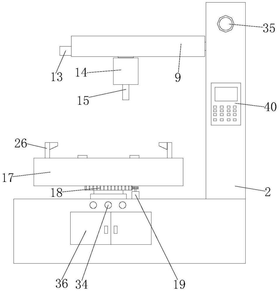
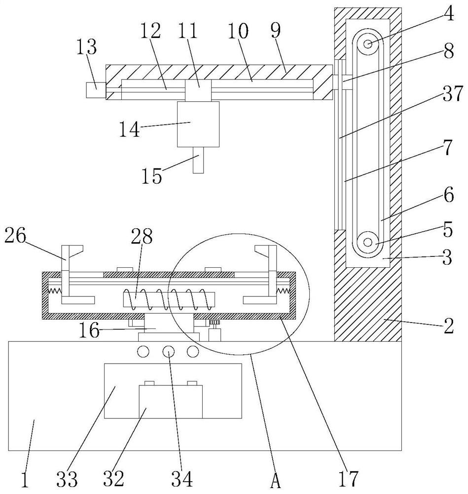
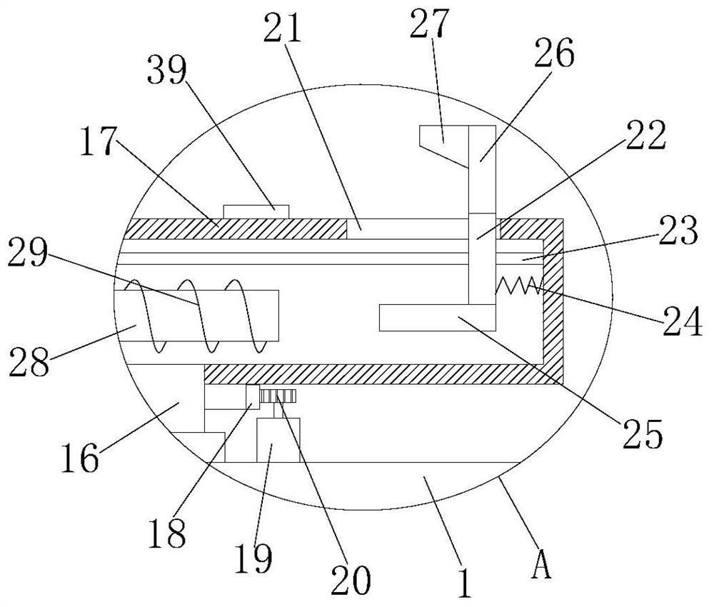
[0030] refer to Figure 1-6 , a surface grinding equipment with a rotating mechanism, including a workbench 1, a vertical plate 2 on the top of the workbench 1, a vertical cavity 3 is opened on the vertical plate 2, a lifting structure is arranged in the vertical cavity 3, and a sliding structure is connected to the lifting structure. Block 8, on the sliding block 8, the horizontal plate 9 is fixedly installed, and the bottom of the horizontal plate 9 is slidably equipped with a grinding motor 14, and the grinding motor 14 is connected with a grinding head 15, and the horizontal plate 9 is connected with an adjustment mechanism, and the adjustment mechanism and the grinding motor 14 connection, a metal pipe 16 is rotatably connected to the workbench 1, and a disk box 17 is fixedly installed on the top of the metal pipe 16. A rotating structure is arranged on the top of the workbench 1. An electromagnet 28 is arranged inside, and a wire 29 is wound on the outside of the electro...

Embodiment 2

[0041] refer to Figure 1-6 , a surface grinding equipment with a rotating mechanism, including a workbench 1, a vertical plate 2 on the top of the workbench 1, a vertical cavity 3 is opened on the vertical plate 2, a lifting structure is arranged in the vertical cavity 3, and a sliding structure is connected to the lifting structure. block 8, on the sliding block 8, a transverse plate 9 is fixedly installed by welding, and a grinding motor 14 is slidingly installed on the bottom of the transverse plate 9, and a grinding head 15 is connected on the grinding motor 14, and the grinding head 15 can be easily replaced. There is an adjustment mechanism, the adjustment mechanism is connected with the grinding motor 14, the metal pipe 16 is connected with the rotation on the workbench 1, the top of the metal pipe 16 is fixedly installed with the disc box 17 by welding, the top of the workbench 1 is provided with a rotating structure, and the rotating structure Connect with the disc b...


PUM


Abstract

The invention belongs to the technical field of plane grinding, particularly relates to plane grinding equipment with a rotating mechanism. The plane grinding equipment aims at solving the problems that in the using process of an existing plane grinding device, due to the fact that a workpiece at the upper end of a circular workbench cannot rotate, consequently, the workpiece cannot be effectivelyground, and the workpiece is inconvenient to fix. Based on the following scheme, the plane grinding equipment comprises a workbench and a top vertical plate of the workbench, a vertical cavity is formed in the vertical plate, a lifting structure is arranged in the vertical cavity, a sliding block is connected to the lifting structure, a transverse plate is fixedly installed on the sliding block,a grinding motor is installed at the bottom of the transverse plate in a sliding mode, a grinding head is connected to the grinding motor, an adjusting mechanism is connected to the transverse plate,the adjusting mechanism is connected with the grinding motor, a metal pipe is rotationally connected to the workbench, and a disc box is fixedly installed at the top of the metal pipe. The plane grinding equipment is convenient to operate, a workpiece is conveniently fixed, meanwhile, the workpiece can be driven to rotate, grinding is convenient, and therefore, the grinding efficiency is improved.

Description

technical field [0001] The invention belongs to the technical field of plane grinding, and in particular relates to a plane grinding equipment with a rotating mechanism. Background technique [0002] Surface grinding is mainly used for grinding planes, grooves, etc. on surface grinding machines. There are two types of surface grinding: the grinding of the outer circular surface of the grinding wheel is called peripheral grinding. Generally, horizontal axis surface grinding machines are used. For example, forming grinding wheels are also used. Various forming surfaces can be processed; grinding with a grinding wheel is called end grinding. [0003] During the use of the existing surface grinding device, since the workpiece at the upper end of the circular workbench cannot be rotated, the workpiece cannot be effectively polished, resulting in uneven grinding of the workpiece, resulting in problems with the quality of the workpiece, and it is inconvenient to fix the workpiece. ...

Claims


Application Information

Patent Timeline
Patent Type & Authority Applications(China)
IPC IPC(8): B24B7/07B24B41/06B24B41/00B24B47/12
CPCB24B7/07B24B41/00B24B41/06B24B47/12
Inventor 江先庆
Owner 江先庆
Why Eureka
Try Eureka