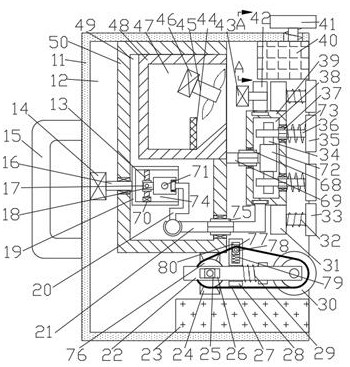
[0015] Combine below Figure 1-4 The present invention is described in detail, wherein, for the convenience of description, the orientations mentioned below are defined as follows: figure 1 The up, down, left, right, front and back directions of the projection relationship itself are the same.
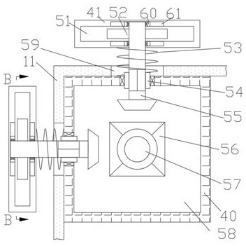
[0016] A hand-held automatic dust-absorbing wall grinding device according to the present invention includes a box body 11, and a cavity 12 with an opening on the right side is provided in the box body 11, and the upper inner wall and the rear side of the cavity 12 are The inner wall is fixed with two symmetrical auxiliary boxes 40, the auxiliary box 40 is provided with an auxiliary chamber 58, and the inner wall of the auxiliary chamber 58 is rotatably connected with two spline sleeves 54 symmetrical to the diagonal of the auxiliary box 40 , the spline sleeve 54 is spline-connected with a rotating shaft 55 extending away from the diagonal side of the auxiliary case 40, and the intersection of the two rotating shafts 55 is provided with a main shaft 57 located in the auxiliary cavity 58, so The right side of the main shaft 57 is rotatably connected with a motor 56 fixed to the inner wall on the right side of the auxiliary chamber 58, and the outer side of the rotating shaft 55 is provided with a hollow groove 59 that runs through the inner wall of the cavity 12, and the rotating shaft 55 is far away from the auxiliary box. A grinding block 41 is provided on one side of the diagonal line of 40, and a spring 53 surrounding the rotating shaft 55 is arranged between the side of the grinding block 41 close to the diagonal line of the auxiliary box 40 and the auxiliary box 40. The block 41 is provided with a grinding cavity 51, and the grinding cavity 51 is provided with a rotating block 52 fixed on the rotating shaft 55 and symmetrical to the left and right, and the grinding block 41 is provided with two chutes symmetrical to the rotating block 52 61, the inner wall of the chute 61 is slidably connected with a moving block 60 rotatably connected to the rotating shaft 55, and the upper inner wall of the cavity 12 is fixed with a fixed box 50 located on the left side of the auxiliary box 40, and the fixed box 50 is provided with a fixed cavity 49, the right side of the fixed box 50 is provided with a rotary box 39, the rotary box 39 is provided with a rotary cavity 38, and the inner wall of the rotary cavity 38 is rotatably connected with a secondary spline sleeve 68, The secondary spline sleeve 68 is spline-connected with a fixed shaft 69 fixed on the right side of the fixed box 50, and two fixed blocks 31 that are vertically symmetrical about the fixed shaft 69 are fixed on the outer side of the rotating box 39. The fixed block 31 is slidably connected with an extension shaft 62 extending to the right, the right side of the extension shaft 62 is provided with a shaking box 33, and the left side of the shaking box 33 and the fixed block 31 are provided with a ring around the extension shaft 62. The secondary spring 32 of the shaking chamber 33 is provided with a shaking chamber 64, the inner wall on the left side of the shaking chamber 64 is slidably connected to the extension shaft 62, and the inner wall on the left side of the shaking chamber 64 is hinged to extend to the right and is located at the The connecting rod 67 on the front side of the extension shaft 62, the main motor 63 is fixed on the right side of the connecting rod 67, and the front side of the main motor 63 is rotatably connected with an irregular wheel 66, and the upper and lower sides of the rotating shaft 55 are connected with the shaking chamber Two engagement springs 65 that are vertically symmetrical about the engagement rod 67 are arranged between the upper and lower inner walls of 64, and a dust suction driving device 901 for dust suction and reciprocating movement is provided in the fixed cavity 49, and the lower side of the cavity 12 An ash removal device 902 for ash removal is provided.
[0017] Beneficially, the dust suction driving device 901 includes a dust suction box 48 fixed on the right inner wall of the fixed cavity 49, and the dust suction box 48 is provided with a dust suction cavity 47 penetrating through the right inner wall of the fixed cavity 49 An auxiliary motor 46 is fixed on the inner wall of the rear side of the dust collection chamber 47, and a fan 45 is connected to the right side of the auxiliary motor 46 for rotation, a filter screen 44 is fixed on the inner wall of the lower side of the dust collection chamber 47, and the left side of the fixed chamber 49 The side inner wall is rotatably connected with an auxiliary rotating shaft 16 extending left and right, and the left side of the auxiliary rotating shaft 16 is rotatably connected with a fixed motor 14 fixed on the inner wall on the left side of the cavity 12, and the right side of the auxiliary rotating shaft 16 is fixed on the fixed motor 14. The power box 19 in the chamber 49, the power box 19 is provided with a power chamber 74 with a right opening, the inner wall of the lower side of the power chamber 74 is fixed with a drive motor 70, and the upper side of the drive motor 70 is connected with a threaded rod for rotation 13. The threaded rod 13 is threadedly connected with a sleeve 17, and the sleeve 17 is rotatably connected with a rotating drum 18, and the rotating drum 18 is rotatably connected with fixing pins 71 fixed on the front and rear inner walls of the power chamber 74. The right side of the drum 18 is rotatably connected with a transmission rod 20, and the lower side of the transmission rod 20 is slidably connected with a sliding rod 21 whose vertical section is slidably connected to the rotating box 39, and the horizontal section of the sliding rod 21 is splined and connected to the rotating box. The spline sleeve 75 on the inner wall on the right side of the fixed cavity 49, the fixed motor 14 makes the auxiliary shaft 16 rotate, the auxiliary shaft 16 drives the power box 19 to rotate, and the transmission rod 20 makes the The sliding rod 21 moves slightly, and the driving motor 70 makes the threaded rod 13 rotate, so that the sleeve 17 moves up and down, so that the rotating cylinder 18 rotates around the fixed pin 71, and the transmission rod 20 makes the The range of movement and rotation of the sliding rod 21 increases, the range of movement of the rotating box 39 increases, and the auxiliary motor 46 rotates the fan 45 to suck dust into the dust suction cavity 47 .
[0018]Beneficially, the dust removal device 902 includes a dust removal motor 24 fixed on the lower side of the fixed box 50, the front side of the dust removal motor 24 is rotatably connected to a pulley 76, and the front side of the pulley 76 is provided with a connecting rod 22, so The connecting rod 22 is provided with a sliding groove 26, the inner wall of the sliding groove 26 is slidably connected with a slider 25 that is rotatably connected to the pulley 76, and the connecting rod 22 is slidably connected with a sliding block fixed on the inner wall of the cavity 12 rear side. And be positioned at the fixing plate 28 on the right side of the dust removal motor 24, the fixing plate 28 is provided with a vertical groove 80 on the upper side of the connecting rod 22, the inner wall of the vertical groove 80 is slidably connected with a secondary slider 77, the A compression spring 79 is provided between the lower side of the auxiliary slider 77 and the inner wall of the vertical groove 80 , the front side of the auxiliary slider 77 is rotatably connected with a transmission wheel 78 , and the fixed plate 28 and the connecting rod 22 are provided with a compression spring 79 . There is a main spring 29 surrounding the connecting rod 22, the right side of the connecting rod 22 is rotated and connected with a rolling brush 30, and the rolling brush 30 is connected with the belt pulley 76 and the transmission pulley 78 through a belt 27, so The inner wall of the lower side of the cavity 12 is fixed with a dustbin 23 located on the lower side of the connecting rod 22, the dust removal motor 24 makes the pulley 76 rotate, and the pulley 76 makes the roller brush 30 rotate through the belt 27 , the grinding dust is collected into the dustbin 23, the connecting rod 22 can move along the fixed plate 28, and the compression spring 79 makes the auxiliary slider 77 slide along the inner wall of the vertical groove 80 , the transmission wheel 78 has the effect of a tensioning wheel.
[0019] Beneficially, the right side of the empty slot 59 is fixed with a fixed wheel 72 located in the rotating cavity 38, and the fixed wheel 72 is meshed with two engaging wheels 34 that are vertically symmetrical about the fixed axis 69. The wheel 34 is fixed with an engaging shaft 36 extending to the right, and the engaging shaft 36 is splined connected with a secondary spline sleeve 37 that is rotatably connected to the inner wall on the right side of the rotating cavity 38, and the right side of the engaging shaft 36 is fixed with a The friction plate 35 on the right side of the rotating box 39 is provided with a return spring 73 surrounding the connecting shaft 36 between the friction plate 35 and the rotating box 39, and the upper side of the rotating box 39 is meshed with a driving wheel 42, the left side of the drive wheel 42 is rotatably connected with a power motor 43 fixed on the rear inner wall of the cavity 12, and a vertically symmetrical handle 15 is fixed on the left side of the box body 11.
[0020] Combine the following Figure 1 to Figure 4 The use steps in this article are described in detail: Initially, the fixed motor 14, the auxiliary motor 46, the dust removal motor 24, the power motor 43, the motor 56, and the main motor 63 are in the closed state, and the spring 53, the return spring 73, and the auxiliary spring 32 , the compression spring 79, the main spring 29 is in a compressed state, the upper connecting spring 65 is in a stretched state, and the lower connecting spring 65 is in a compressed state.
[0021] When working, hold the handle 15 with your hand so that the box body 11 touches the wall that needs to be polished, start the fixed motor 14, make the auxiliary rotating shaft 16 rotate, drive the power box 19 to rotate, and make the sliding rod 21 slightly move left and right through the transmission rod 20, Make the rotary box 39 drive the secondary spline sleeve 68 to move slightly left and right along the fixed shaft 69, start the drive motor 70, make the threaded rod 13 rotate, and at the same time make the sleeve 17 move upwards along the threaded rod 13, so that the rotating cylinder 18 winds around the fixed pin 71 rotates at a certain angle, because the power box 19 rotates so that the swing range of the transmission rod 20 is too large, and at the same time the range of the reciprocating motion of the sliding rod 21 is increased, so that the range of the reciprocating motion of the rotating box 39 is increased, so that the protrusion on the wall There is a better grinding effect, start the power motor 43, make the driving wheel 42 rotate, and make the rotating box 39 rotate at the same time, the rotating box 39 rotates to drive the connecting shaft 36 to rotate, and because the meshing between the connecting wheel 34 and the fixed wheel 72 simultaneously, make The connecting shaft 36 rotates in the opposite direction. At this time, the friction plate 35 is polished to the wall surface. The contraction of the return spring 73 makes the friction plate 35 more effectively pressed on the wall surface, and the wall is polished. The rotating box 39 rotates at the same time It will make the fixed block 31 rotate together, and when the box body 11 is pushed to the wall by hand, the return spring 73 will be compressed, and the auxiliary spring 32 will be compressed at the same time, and the extension shaft 62 will slide along the inner wall on the left side of the shake chamber 64 to start The main motor 63 can make the irregular wheel 66 rotate, and at the same time, the main motor 63 can drive the irregular wheel 66 to shake up and down under the action of the connecting spring 65, and simultaneously drive the connecting rod 67 to swing up and down, so that the shaking box 33 as a whole shakes, which is convenient for The grinding of the wall surface, when meeting a right-angled wall, the grinding block 41 on one side can be made to touch the right angle of the wall corner, and the rotating shaft 55 can slide along the spline sleeve 54 under the action of manpower, and the motor 56 can be started to make the main shaft 57 Rotate, when the rotating shaft 55 is engaged with the motor 56, the rotating shaft 55 is rotated, and the spring 53 at this time is compressed, because the rotating shaft 55 rotates, the rotating block 52 is rotated. Engagement makes the grinding block 41 move left and right, and the moving block 60 slides left and right along the inner wall of the chute 61. At this time, the grinding block 41 grinds one side of the right-angled wall. Similarly, the grinding block 41 on the other side also needs to be manually After being pressed on the wall, the right-angle wall is polished, and the dust after polishing can float in the cavity 12, start the auxiliary motor 46, and the fan 45 is rotated, and the fan 45 makes the dust suck in the dust suction chamber 47, and then the dust will be sucked into the dust suction chamber 47. The filter screen 44 is blocked in the dust suction chamber 47, and a large amount of lime will fall when the wall is polished, and the dust removal motor 24 is started to make the belt pulley 76 rotate, and the roller brush 30 is rotated by the belt 27, so that the lime is swept into the dustbin 23, and The main spring 29 is compressed when the box body 11 abuts against the wall, and the connecting rod 22 moves to the left along the fixed plate 28, and the slider 25 slides along the inner wall of the sliding groove 26, and the compression spring 79 makes the driving wheel 78 move along the vertical direction. Slot 80 inner wall sliding , the driving wheel 78 is a tensioning wheel, so that the belt 27 is tensioned.
[0022] When finishing, remove the dust in dustbin 23 and dust suction chamber 47, close fixed motor 14, secondary motor 46, dedusting motor 24, power motor 43, motor 56, main motor 63.
[0023] The beneficial effects of the present invention are: the present invention adopts the method of manually pushing the device against the wall to polish the wall, and adopts a grinding method with different diameters and opposite grinding directions for the grinding of the wall plane, which is conducive to fully grinding the wall , and the device has the function of grinding right-angled wall corners, and at the same time has the function of collecting floating dust and lime. The device is simple and practical, and is convenient for grinding.
[0024] The above-mentioned embodiments are only to illustrate the technical concept and characteristics of the present invention, and the purpose is to enable those skilled in the art to understand and implement the present invention, and not to limit the protection scope of the present invention. All equivalent changes or modifications made according to the spirit of the present invention shall fall within the protection scope of the present invention.