Sewage treatment equipment for livestock breeding
A technology for sewage treatment equipment and water outlet pipes, which is applied in the fields of animal husbandry wastewater treatment, water/sewage treatment, water/sewage multi-stage treatment, etc. Advanced problems, to achieve the effect of optimizing the filtering effect, reducing the workload, and facilitating processing
- Summary
- Abstract
- Description
- Claims
- Application Information
AI Technical Summary
Problems solved by technology
Method used
Image
Examples
Embodiment 1
[0031] A kind of sewage treatment equipment for animal husbandry, such as figure 1 , figure 2 , image 3 , Figure 4 As shown, it includes a base 1, a support column 2, a collection box 3, an outlet pipe 4, a discharge frame 5, a filter frame 6, a catalytic mechanism 7, and a filter mechanism 8. The base 1 is provided with a collection box 3, and the right side of the collection box 3 A water outlet pipe 4 is provided on the side, a support column 2 is provided on the rear side of the base 1, a discharge frame 5 is provided on the upper part of the support column 2, a filter frame 6 is provided in the middle of the support column 2, and a catalytic mechanism 7 is provided on the discharge frame 5. A filter mechanism 8 is provided on the filter frame 6 .
[0032] First, pour the sewage that needs to be treated into the discharge frame 5, and pour the catalyst into the catalytic mechanism 7. When a certain amount of sewage is poured, the catalytic mechanism 7 will start to o...
Embodiment 2
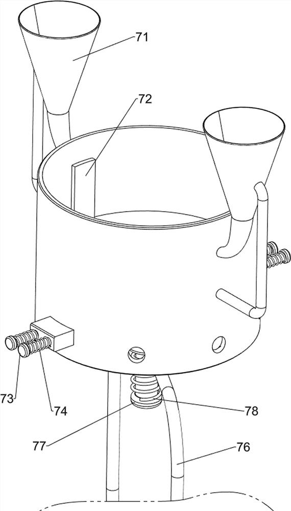
[0034] On the basis of Example 1, such as figure 1 , figure 2 , image 3 , Figure 4 As shown, the catalytic mechanism 7 includes a discharge bucket 71, a baffle plate 72, a first wedge block 73, a first spring 74, an iron pipe 75, a U-shaped frame 76, a pressing plate 77 and a second spring 78, and the discharge frame 5 is left or right. The discharge barrel 71 is symmetrically arranged, the sliding type in the discharge frame 5 is provided with a baffle plate 72, the bottom of the baffle plate 72 is provided with a pressing plate 77, and the front and rear symmetrical sliding type of the discharge frame 5 is provided with a first wedge-shaped block 73, the first wedge-shaped block 73 is equipped with a first spring 74 symmetrically left and right, iron pipe 75 is evenly arranged on the lower part of the discharge frame 5, a U-shaped frame 76 is arranged on the filter frame 6, and the middle bottom of the U-shaped frame 76 is slidably connected with the pressing plate 77, ...
Embodiment 3
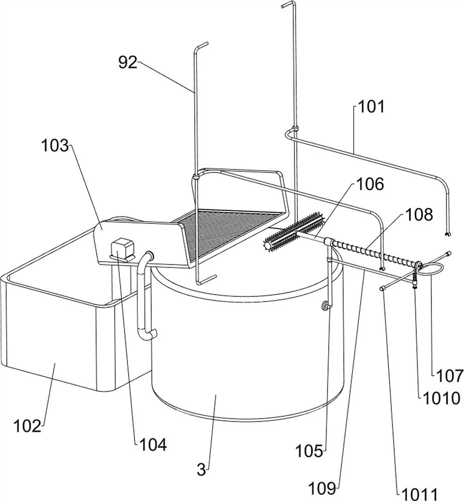
[0039] On the basis of Example 2, such as Figure 5 , Image 6 , Figure 7 , Figure 8 As shown, it also includes a material-related mechanism 9, the first connecting column 81 is provided with a material-related mechanism 9, and the material-closed mechanism 9 includes a first sliding sleeve 91, a second sliding rod 92, an upper wedge 93 and a lower wedge 94, The filter frame 6 is symmetrically provided with a first sliding sleeve 91 front and rear, and a second sliding rod 92 is slidably provided in the first sliding sleeve 91. The bottom of the second sliding rod 92 is connected with the first sliding rod 82, and the second sliding rod 92 An upper wedge-shaped block 93 is symmetrically arranged on the upper side, and a lower wedge-shaped block 94 is arranged symmetrically on the outer side of the first wedge-shaped block 73 .
[0040] When the first sliding bar 82 moves downward, it will drive the second sliding bar 92 to move downward, thereby driving the upper wedge 93...
PUM
 Abstract
Description
Claims
Application Information
 - R&D
- Intellectual Property
- Life Sciences
- Materials
- Tech Scout
- Unparalleled Data Quality
- Higher Quality Content
- 60% Fewer Hallucinations
Browse by: Latest US Patents, China's latest patents, Technical Efficacy Thesaurus, Application Domain, Technology Topic, Popular Technical Reports.
© 2025 PatSnap. All rights reserved.Legal|Privacy policy|Modern Slavery Act Transparency Statement|Sitemap|About US| Contact US: help@patsnap.com


