Supercharge Your Innovation With Domain-Expert AI Agents!

Optical module and laser module

A technology of optical modules and laser light sources, which is applied in optics, optical components, instruments, etc., can solve the problems of uncompact optical system structure, limited requirements for light source wavelength and light source type, large light outlet size, etc., and achieve various forms of light spots The effect of modernization, compact structure and low cost

Active Publication Date: 2021-01-01
FOCUSLIGHT TECH
View PDF7 Cites 2 Cited by
  • Summary
  • Abstract
  • Description
  • Claims
  • Application Information

AI Technical Summary

Problems solved by technology

[0003] However, the above two methods have their disadvantages. When the DOE element realizes the superposition of point-like spots, there are restrictions on the wavelength of the light source and the type of light source; and the placement angle of the light source will lead to an uncompact structure of the entire optical system and a large size of the light outlet.

Method used


Image

  • Optical module and laser module
  • Optical module and laser module
  • Optical module and laser module

Examples


Embodiment Construction

[0038] In order to make the purpose, technical solutions and advantages of the embodiments of the present invention clearer, the technical solutions in the embodiments of the present invention will be clearly and completely described below in conjunction with the drawings in the embodiments of the present invention. Obviously, the described embodiments It is a part of embodiments of the present invention, but not all embodiments. The components of the embodiments of the invention generally described and illustrated in the figures herein may be arranged and designed in a variety of different configurations.

[0039] Accordingly, the following detailed description of the embodiments of the invention provided in the accompanying drawings is not intended to limit the scope of the claimed invention, but merely represents selected embodiments of the invention. Based on the embodiments of the present invention, all other embodiments obtained by persons of ordinary skill in the art wi...


PUM


Abstract

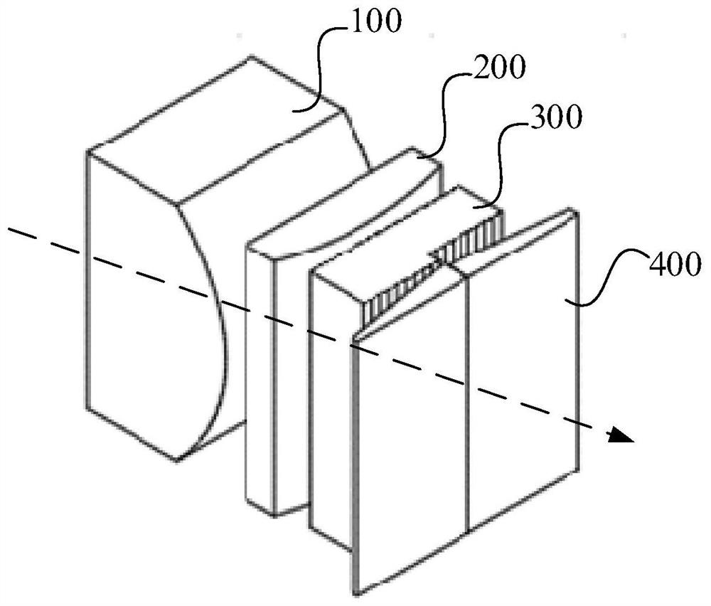
The invention provides an optical module and a laser module, and belongs to the technical field of light spot superposition. The optical module comprises an array lens group and a wedge-shaped lens group which are sequentially arranged along a main optical axis, the array lens group comprises a first array lens and a second array lens which are sequentially arranged along a first direction perpendicular to the main optical axis, and the wedge-shaped lens group is arranged at the light emitting side of the first array lens and / or the second array lens. Laser beams form angular space flat-toppedlight spots with different beam angles through the array lens group, and the angular space flat-topped light spots are refracted by the wedge-shaped lens group and then form angular space superposedlight spots in a far field. By arranging the array lens group and the wedge-shaped lens group, and according to different change combinations of the array lens group and the wedge-shaped lens group, superposed light spots with different effects can be formed, the light spot forms are diversified, the flexibility is high, different requirements can be met; different light spot superposition is achieved through the three optical elements, and the optical module is compact in structure, small in size and low in cost, and has few limitation to a light source.

Description

technical field [0001] The present invention relates to the technical field of spot superposition, in particular to an optical module and a laser module. Background technique [0002] At present, Lidar (Lidar) mainly implements the application of superimposed spots in two ways: one is through the diffraction element (DOE), such as the diffraction element disclosed in patent 201811051292.6 and its application in the Lidar system, with the help of incoherent laser When illuminated independently of each other, non-interfering diffraction patterns are generated in the far field as the total diffraction pattern. The other is to oscillate the light source so that the light source is irradiated at different angles to realize the superposition of far-field laser beams. [0003] However, the above two methods have their disadvantages. When the DOE element realizes the superimposition of point-like spots, there are restrictions on the wavelength and type of the light source; and the ...

Claims


Application Information

Patent Timeline
IPC IPC(8): G02B27/09
CPCG02B27/0961G02B27/095G02B27/48
Inventor 蔡磊李勇
Owner FOCUSLIGHT TECH
Features
  • R&D
  • Intellectual Property
  • Life Sciences
  • Materials
  • Tech Scout
  • Unparalleled Data Quality
  • Higher Quality Content
  • 60% Fewer Hallucinations
Learn More