Power cable stripping device for electric power engineering

A power cable and power engineering technology, which is applied to cable installation devices, cable installation, and equipment for dismantling/armored cables, etc., can solve the problem of low peeling sufficiency, etc. Wide range, improved peeling effect

Inactive Publication Date: 2021-01-01
杨浩
View PDF1 Cites 7 Cited by
  • Summary
  • Abstract
  • Description
  • Claims
  • Application Information

AI Technical Summary

Problems solved by technology

The invention drives the power cable to move linearly through the moving device, thereby reducing the labor intensity of the staff. During the movement of the power cable, the upper and lower sides of the power cable are simultaneously cut by the cutting device. The stripping devices on the left and right sides cut

Method used


Image

  • Power cable stripping device for electric power engineering
  • Power cable stripping device for electric power engineering
  • Power cable stripping device for electric power engineering

Examples


Embodiment 1

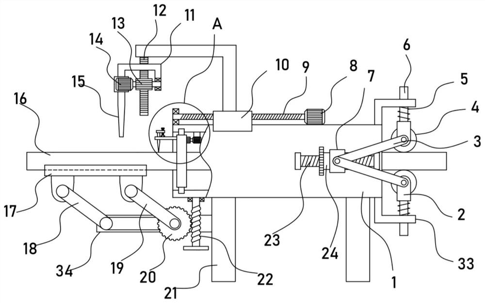
[0022] see Figure 1-3 , a power cable stripping device for electric power engineering, comprising a horizontal pipe 1, a support column 21 is vertically fixed at the bottom of the horizontal pipe 1, a power cable 16 runs through the horizontal pipe 1, and a fixing plate 34 is fixed on the support column 21 , the fixed plate 34 is equipped with an arc-shaped supporting plate 17 for carrying the power cable 16 through a supporting mechanism, and the horizontal tube 1 is driven and connected with a vertically arranged vertical rack 12 through a translation mechanism. 12 is connected with an axial cutting mechanism for axially cutting the power cable 16. The horizontal pipe 1 is driven and rotated by a rotating mechanism to install an inner ring gear 29, which is installed on the inner ring gear 29 for cutting the power cable 16 a circular cutting mechanism for circumferential cutting, the horizontal pipe 1 is provided with a clamping mechanism for clamping the power cable 16 . ...

Embodiment 2

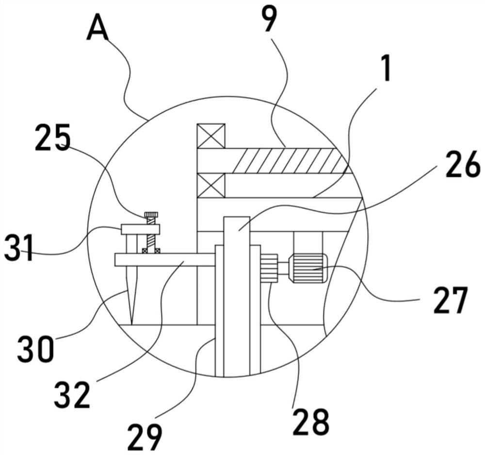
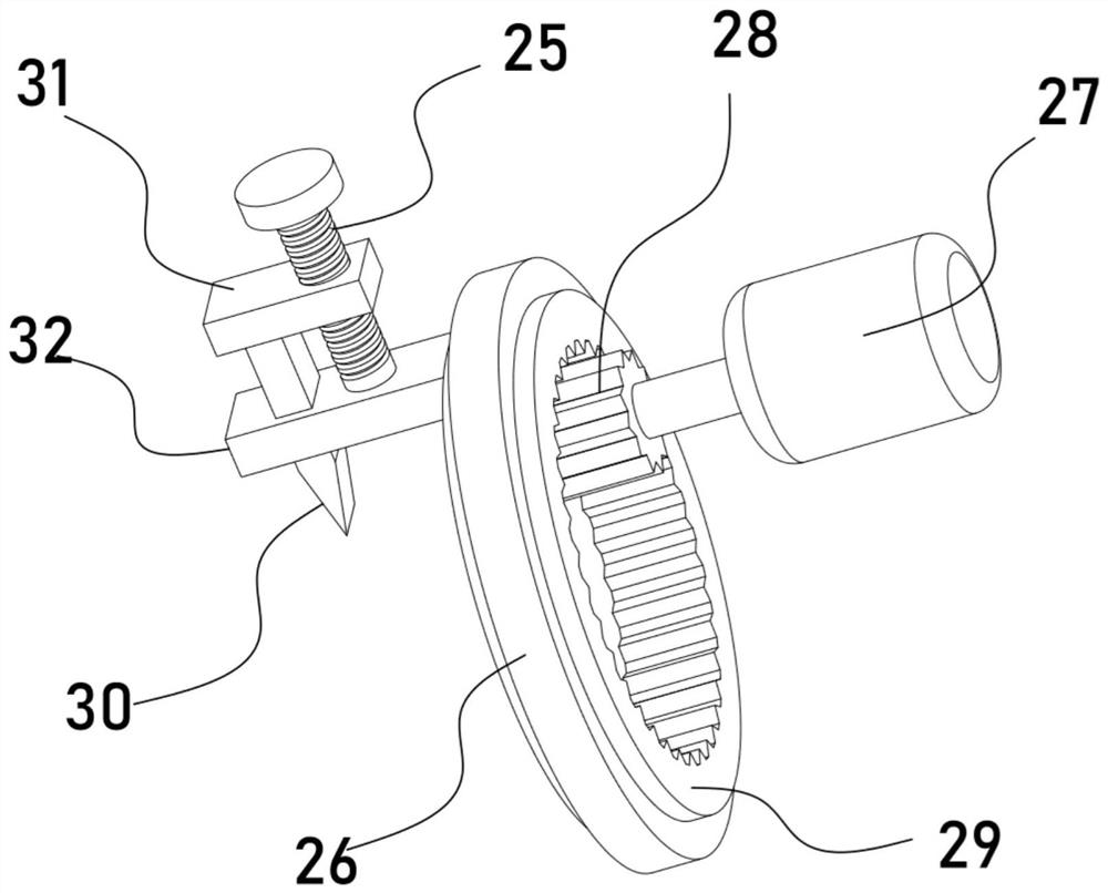
[0029] On the basis of Embodiment 1, in addition, this device is also provided with a circular cutting mechanism, including an inner ring gear 29 rotatably installed in the horizontal tube 1, a support plate 32 is fixed on the inner ring gear 29, and a vertical The circular cutting blade 30 is installed in a straight slide, and the upper end of the circular cutting blade 30 is fixed with a horizontal plate 31. The upper end of the horizontal plate 31 is screwed with a lower end bearing connected to the adjusting stud 25 installed on the support plate 32. The circular cutting mechanism also includes a fixed The driving motor 27 in the horizontal pipe 1 is driven and connected to the driving gear 28, and the driving gear 28 is meshed with the inner ring gear 29. The outer wall of the inner ring gear 29 is fixed with a ring sliding embedded in the inner wall of the horizontal pipe 1 The ring to cover block 26.

[0030] After the sheath of the power cable 16 is cut by the axial cu...


PUM


Abstract

The invention discloses an electric power cable stripping device for electric power engineering, and relates to the technical field of electric power engineering. The electric power cable stripping device comprises a horizontal pipe, a vertical rack is in transmission connection with an axial cutting mechanism used for axially cutting an electric power cable, and an inner gear ring is rotationallyinstalled in the horizontal pipe under the driving of a rotating mechanism; an annular cutting mechanism used for annularly cutting the power cable is installed on the inner gear ring, and a clampingmechanism used for clamping the power cable is arranged on the horizontal pipe; according to the power cable stripping device, the arranged axial cutting mechanism can axially cut the sheath of the power cable, and the arranged circumferential cutting mechanism can circumferentially cut the power cable, so that the sheath of the power cable can be smoothly separated from the main body, and the stripping effect of the sheath of the power cable is remarkably improved; the device can achieve a flexible adjustment effect according to power cables with different diameters and peeling areas of thepower cables, is wide in application range, and is very high in peeling stability and peeling quality.

Description

technical field [0001] The invention relates to the technical field of electric power engineering, in particular to a power cable stripping device for electric power engineering. Background technique [0002] Electric power engineering refers to engineering related to the production, transmission, and distribution of electric energy. In a broad sense, it also includes engineering that uses electricity as power and energy in various fields. At the same time, it can be understood that the power transmission and transformation industry expansion project. In the construction of power network, cables often need to go through various treatments before they can be applied to the power network, and the cables can be stripped by the peeling mechanism. [0003] The patent application publication No. CN110649520 A discloses a power cable stripping device for electric power engineering, including a workbench and a cutting device. Above the first support plate, the workbench is provide...

Claims


Application Information

Patent Timeline
IPC IPC(8): H02G1/12
CPCH02G1/1268
Inventor 杨浩
Owner 杨浩
Why Eureka
Try Eureka