Efficient chemical mixing device

A mixing device and chemical technology, applied in the field of high-efficiency chemical mixing devices, can solve the problems of low mixing efficiency, single operation mode, general material mixing effect, etc., and achieve the effect of improving the mixing effect.

Inactive Publication Date: 2021-01-05
周光斌
View PDF8 Cites 0 Cited by
  • Summary
  • Abstract
  • Description
  • Claims
  • Application Information

AI Technical Summary

Problems solved by technology

However, the design of the mixing mechanism of the above-mentioned patent is relatively simple, and the operation mode during operation is relatively simple. In actual operation, the mixing effect of materials is relatively general and the mixing efficiency is low, so there are certain limitations.

Method used


Image

  • Efficient chemical mixing device
  • Efficient chemical mixing device
  • Efficient chemical mixing device

Examples


Embodiment 1

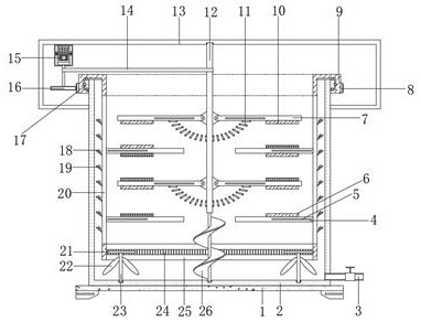
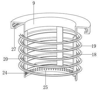
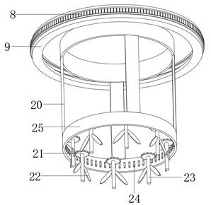
[0030] refer to Figure 1-4 , a high-efficiency chemical mixing device, comprising a base 1 with legs welded at the four corners of the bottom outer wall, a mixing box 2 fixed on the top outer wall of the base 1 by bolts, and a reinforcing ring plate 17 welded on the peripheral outer wall of the mixing box 2 near the top , and the outer wall of the reinforcing ring plate 17 is clamped with a supporting ring 9, and the opposite side of the supporting ring 9 and the reinforcing ring plate 17 is provided with an annular groove 27, and the inner walls of the corresponding two annular grooves 27 are rollingly connected with equidistantly distributed The four corners of the outer wall of the ball and the bottom of the support ring 9 are vertically welded with a fixed lever 4, and the outer wall of the mixing box 2 near the top is welded with a fixed frame 13, and the central axis of the top of the fixed frame 13 is connected with a rotating column 12 through a bearing rotation. , th...

Embodiment 2

[0041] refer to Figure 5 , a high-efficiency chemical mixing device. Compared with Embodiment 1, this embodiment also includes a swing rod 7 and one end of the top outer wall of the fixed driving rod 4. A collection tube 29 is welded, and the collection tube 29 is fixedly connected with a dial tube 28. .

[0042] When the present invention is in use: Utilize the collection cylinder 29 and the dial cylinder 28 arranged on the swing rod 7 and the fixed glass rod 4, during the rotation process of the swing rod 7 and the fixed dial rod 4, the material is first drummed into the dial cylinder 28, And in the collection barrel 29 to achieve collection, impact, to achieve the purpose of further improving the mixing effect of materials.


PUM


Abstract

The invention belongs to the technical field of chemical engineering, particularly relates to an efficient chemical mixing device, and aims to solve the problems that most of traditional chemical mixing devices are single in operation mode, common in actual mixing effect of materials and low in efficiency, and the efficient chemical mixing device comprises a base with supporting legs welded to four corners of the outer wall of the bottom. A mixing box is fixed to the outer wall of the top of the base through bolts, a reinforcing ring plate is welded to the outer wall of the circumference, close to the top end, of the mixing box, a supporting ring is clamped to the outer wall of the reinforcing ring plate, and annular grooves are formed in the sides, opposite to the reinforcing ring plate,of the supporting ring. Through an arranged driving motor, the supporting ring and a rotating column can be driven to rotate oppositely through the transmission effect of a driving gear, a driven gearring and a transmission belt, then opposite rotation of a fixed shifting rod and a swing rod is achieved, and through the attraction and repulsion effects of a first magnetic block and a second magnetic block, and cooperation with a connecting spring, the swing rod is driven to swing up and down along a connecting block rotate in the rotating process to realize an efficient mixing effect.

Description

technical field [0001] The invention relates to the technical field of chemical industry, in particular to a high-efficiency chemical material mixing device. Background technique [0002] Chemical industry is the abbreviation of "chemical technology", "chemical industry" and "chemical engineering". Any technology that uses chemical methods to change the composition and structure of substances or to synthesize new substances belongs to chemical production technology, that is, chemical technology, and the resulting products are called chemicals or chemical products. At first, what produce this series products is handicraft workshop, develops into factory later, and has gradually formed specific production industry, namely a chemical industry. Chemical engineering is a science that studies the general laws of the production process of chemical products. The relationship between human beings and chemical industry is very close. Some chemical products play an epoch-making role ...

Claims


Application Information

Patent Timeline
Patent Type & Authority Applications(China)
IPC IPC(8): B01F11/00B01F15/00
CPCB01F31/443B01F35/43B01F2101/2204
Inventor 周光斌
Owner 周光斌
Why Eureka
Try Eureka