
Method for improving punching stability of photovoltaic glass stepped holes

A technology of photovoltaic glass and stepped holes, which is applied in laser welding equipment, welding equipment, metal processing equipment, etc., can solve the problems of inability to process shaped stepped holes, low precision of stepped holes, limited processing capacity, etc., and achieve optimal laser processing path , Improving the stability of drilling and the effect of high processing accuracy

Pending Publication Date: 2021-01-05
SHENZHEN JIXIANGYUN TECH CO LTD
View PDF6 Cites 2 Cited by
  • Summary
  • Abstract
  • Description
  • Claims
  • Application Information

AI Technical Summary

Problems solved by technology

[0002] Glass step hole drilling is suitable for processing glass products of different materials, specifications, thicknesses, etc. It belongs to the field of glass laser processing and can be widely used in architectural glass, handicraft glass, photovoltaic glass and other industries. The traditional method of processing step holes is to use diamond grinding head at high speed Rotating contact glass material for processing belongs to contact processing, which has the following disadvantages: ① Glass has edge burst and scratch problems; ② Holes smaller than the size of the drill bit cannot be processed; ③ Step holes with complex shapes cannot be processed, and the processing capacity is limited; ④ The stepped part of the stepped hole is not accurate and smooth

Method used


Image

  • Method for improving punching stability of photovoltaic glass stepped holes
  • Method for improving punching stability of photovoltaic glass stepped holes
  • Method for improving punching stability of photovoltaic glass stepped holes

Examples


Embodiment Construction

[0028] The following will clearly and completely describe the technical solutions in the embodiments of the present invention with reference to the accompanying drawings in the embodiments of the present invention. Obviously, the described embodiments are only some, not all, embodiments of the present invention. Based on the embodiments of the present invention, all other embodiments obtained by persons of ordinary skill in the art without making creative efforts belong to the protection scope of the present invention.

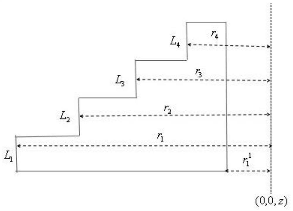
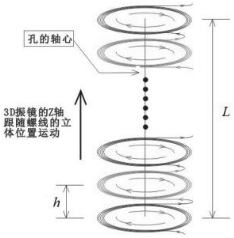
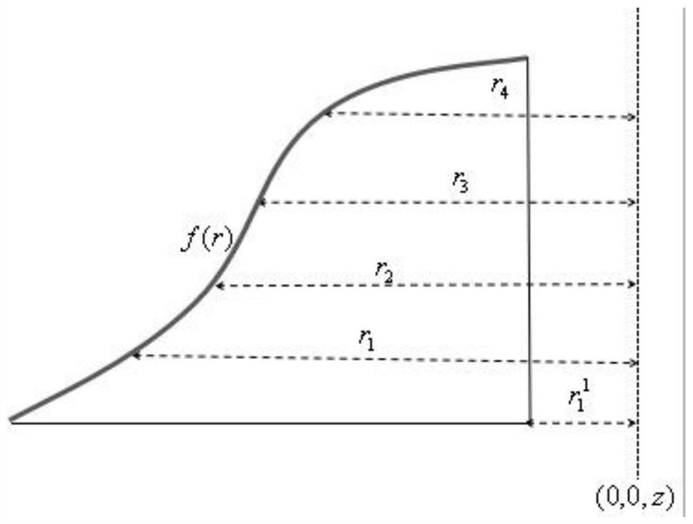
[0029] see Figure 1-3 , in an embodiment of the present invention, a method for improving the stability of punching a step hole in photovoltaic glass, a method for improving the stability of punching a step hole in photovoltaic glass, comprising the following steps:

[0030] Adjust the starting position of the focal point of the 3D galvanometer, focus the laser on the lower surface of the material to be processed, define the coordinate position of this point ...


PUM


Abstract

The invention discloses a method for improving the punching stability of photovoltaic glass stepped holes. The method includes the following steps that the starting point position of a focus of a 3D galvanometer is adjusted, laser is focused to the lower surface of a to-be-machined material, the coordinate positions of the point are defined as (0, 0, 0), and the hole axis coordinates of the to-be-machined material are defined as (0, 0, z); the laser starting point moves to the (r1, 0, 0) position and moves in a spiral line manner with the (0, 0, 0) used as the circle center and the r1 used asthe outer radius; after the laser starting point passes through a layer of spiral line, the focus Z axis controlled by the 3D galvanometer is lifted, and then machining is continued; when the Z axis reaches the second layer, the laser starting point moves to the (r11, 0, h) position and moves in a spiral line manner with the (0, 0, h) used as the circle center and the r11 used as the inner radius,and the advancing direction is changed into a spiral line from inside to outside until the laser passes through the spiral line of the layer; and after the focus Z axis controlled by the 3D galvanometer is lifted, machining is continued, when the Z axis reaches the third layer, the laser starting point moves to the (r1, 0, 2 h) position, and the (0, 0, 2 h) is used as the circle center. Accordingto the method, a product with the smooth hole wall, the high machining precision and the good stability can be obtained.

Description

technical field [0001] The invention relates to the technical field of glass step hole processing, in particular to a method for improving the stability of punching a photovoltaic glass step hole. Background technique [0002] Glass step hole drilling is suitable for processing glass products of different materials, specifications, thicknesses, etc. It belongs to the field of glass laser processing and can be widely used in architectural glass, handicraft glass, photovoltaic glass and other industries. The traditional method of processing step holes is to use diamond grinding head at high speed Rotating contact glass material for processing belongs to contact processing, which has the following disadvantages: ① Glass has edge burst and scratch problems; ② Holes smaller than the size of the drill bit cannot be processed; ③ Step holes with complex shapes cannot be processed, and the processing capacity is limited; ④ The stepped part of the stepped hole is not accurate and smoo...

Claims


Application Information

Patent Timeline
IPC IPC(8): B23K26/382B23K26/402B23K26/70
CPCB23K26/382B23K26/402B23K26/702
Inventor 陈燕杨林黄再福王技科冯建华张勇胡柳平
Owner SHENZHEN JIXIANGYUN TECH CO LTD
Learn More