Connecting structure for fabricated building components
A technology for building components and connecting structures, applied in auxiliary devices, welding equipment, auxiliary welding equipment, etc., can solve problems such as difficult alignment
- Summary
- Abstract
- Description
- Claims
- Application Information
AI Technical Summary
Problems solved by technology
Method used
Image
Examples
Embodiment 1
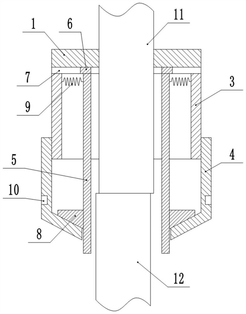
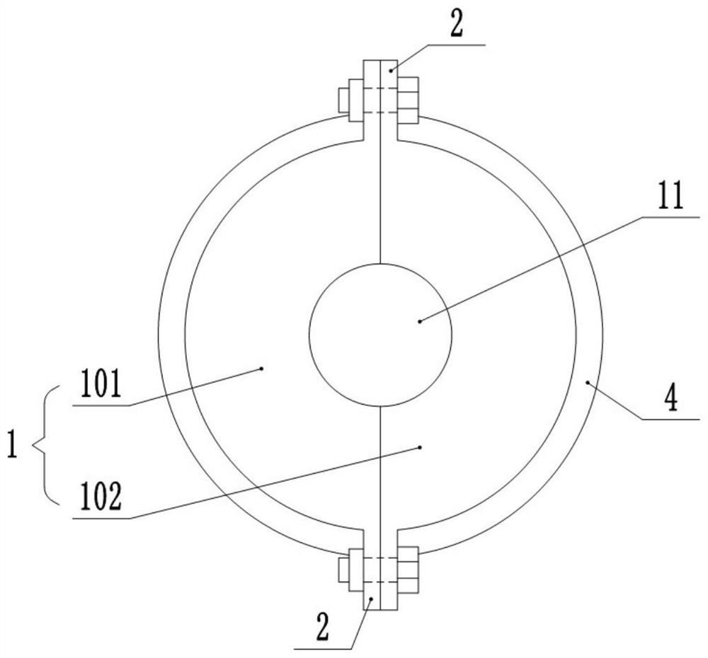
[0031] This embodiment is basically as figure 1 and figure 2 Shown: the connecting structure used for assembled building components, including an annular sleeve 1 sleeved on the outer periphery of the building component, the annular sleeve 1 includes a left half body 101 and a right half body 102, two parts of the left half body 101 and the right half body 102 The ends are integrally formed with ear plates 2, and the ear plates 2 are provided with installation holes. In this embodiment, the user puts the left half body 101 and the right half body 102 respectively on the outer periphery of the upper building component 11, uses bolts to pass through the installation holes, and then tightens the nuts on the bolts, so that the left half body 101 and the right half body 101 and the right half body The half body 102 is fixedly socketed on the outer periphery of the building component, so that the ring sleeve 1 is fixedly socketed on the outer periphery of the building component. ...
Embodiment 2
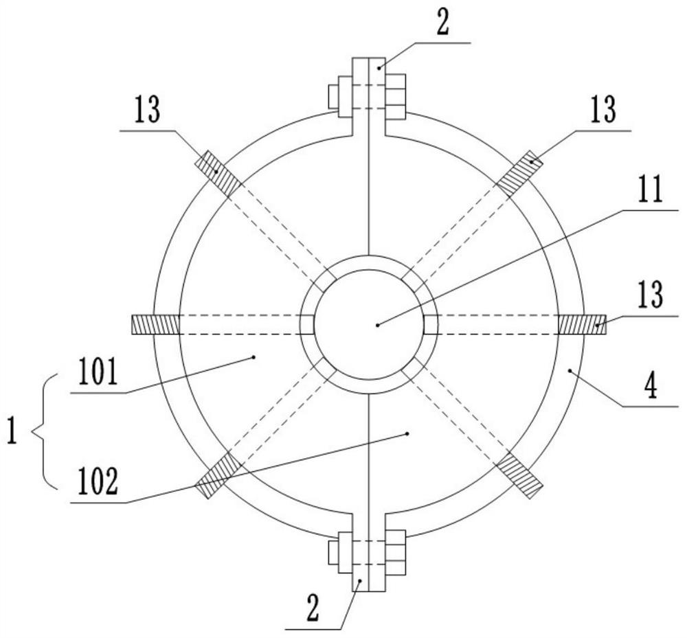
[0039] The difference between this embodiment and the first embodiment is: image 3 As shown, the annular sleeve 1 is provided with a plurality of horizontally arranged threaded holes along the circumferential direction, and the threaded holes are threadedly connected with a pressing threaded rod 13 . In this embodiment, the number of threaded holes is six.
[0040] In this embodiment, since the annular sleeve 1 has six threaded holes and abutting threaded rods 13 in the circumferential direction, the threaded rods 13 are rotated and the ends of the abutting threaded rods 13 are abutted against the outer peripheral wall of the building component. The annular sleeve 1 is fixedly sleeved on building components of different sizes to achieve alignment of building components of different sizes. In addition, the connection structure in this embodiment can also be applied to building components whose radial cross section is rectangular, thereby expanding the application range of the...
Embodiment 3
[0042] The difference between this embodiment and the second embodiment is: Figure 4 As shown, among the six threaded holes, four threaded holes are selected as special threaded holes, and the abutment threaded rod 13 corresponding to the special threaded hole is a special abutment threaded rod 14 . Among the four special threaded holes, the included angle between two adjacent special threaded holes is 90°, and the rotation directions of the opposite two special threaded holes are opposite. A telescopic rod 15 is coaxially connected to the end of each special abutting threaded rod 14. The telescopic rod 15 includes an outer rod 151 and an inner rod 152 that can slide in the axial direction. A plurality of grooves, the inner rod 152 is axially provided with a plurality of sliding bars which are matched with the grooves, and the sliding bars are slidably connected in the grooves.
[0043] The inner rod 152 is welded with the end of the special abutting threaded rod 14 , the ou...
PUM
 Abstract
Description
Claims
Application Information
 - R&D
- Intellectual Property
- Life Sciences
- Materials
- Tech Scout
- Unparalleled Data Quality
- Higher Quality Content
- 60% Fewer Hallucinations
Browse by: Latest US Patents, China's latest patents, Technical Efficacy Thesaurus, Application Domain, Technology Topic, Popular Technical Reports.
© 2025 PatSnap. All rights reserved.Legal|Privacy policy|Modern Slavery Act Transparency Statement|Sitemap|About US| Contact US: help@patsnap.com


