A cutting and capping machine for cables

A cable and wire clamping mechanism technology, applied in metal processing equipment, metal processing, manufacturing tools, etc., can solve the problems of different cable cutting lengths, depths, and large labor, and save labor. , The assembly size is accurate, the effect of saving labor costs

Active Publication Date: 2022-01-11
菱创智能科技(常熟)有限公司
View PDF9 Cites 0 Cited by
  • Summary
  • Abstract
  • Description
  • Claims
  • Application Information

AI Technical Summary

Problems solved by technology

The existing method of adding rubber caps to cables is usually to put the caps on manually by the operator, and the operator manually cuts the wires, then puts the rubber caps on the ends of the cables, and then clamps them with clamps. method, the amount of manual labor is large, the operation speed is slow, and the manual operation, the length of the cable cut is different, and the depth of the rubber cap inserted into the cable is different, resulting in no uniform standard for the production of the cable, which cannot meet the requirements of the cable. Production requirements and needs

Method used


Image

  • A cutting and capping machine for cables
  • A cutting and capping machine for cables
  • A cutting and capping machine for cables

Examples


Embodiment

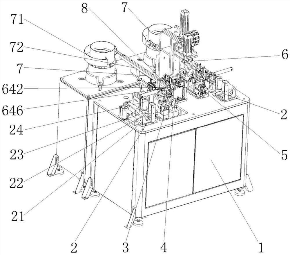
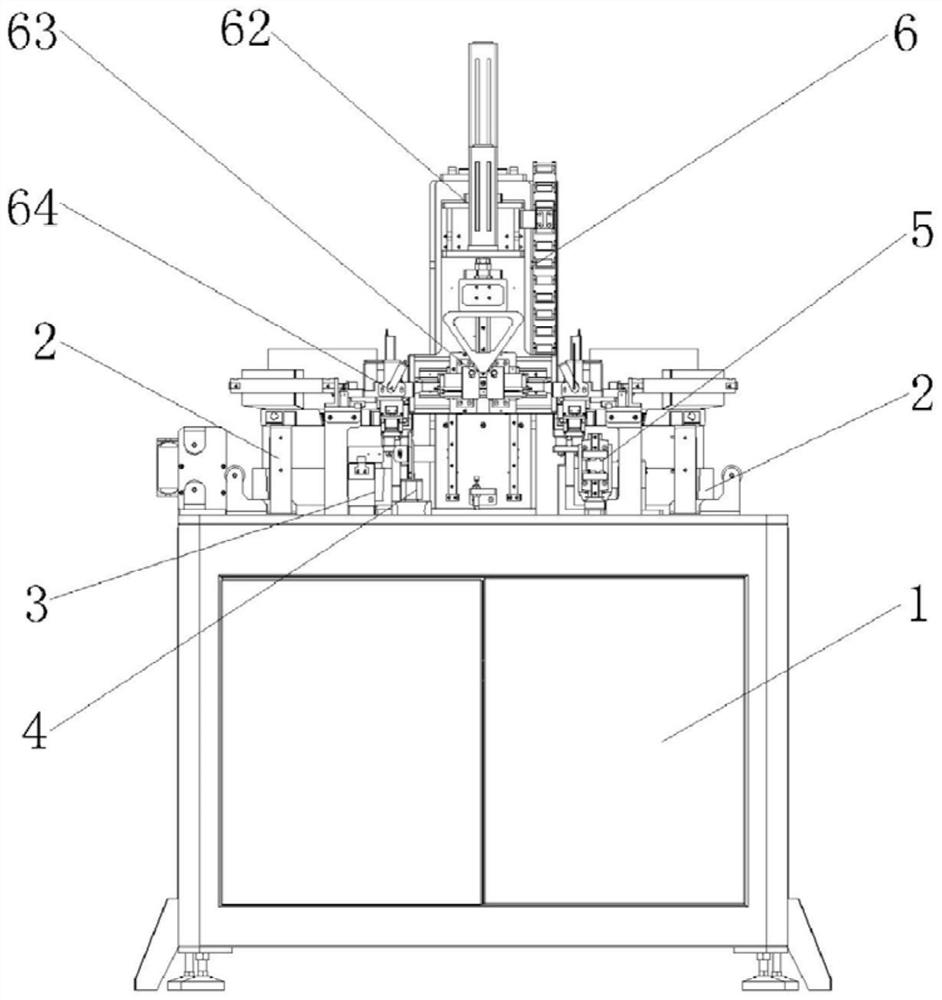
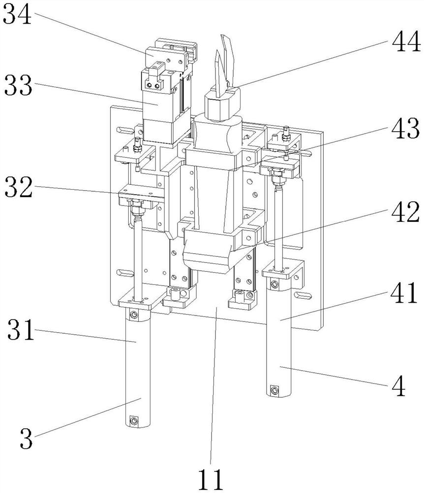
[0029] Such as Figure 1-5 As shown, a cutting and capping machine for cables includes a chassis 1, and the upper front side of the chassis 1 is sequentially provided with a cable guiding mechanism 2, a first clamping mechanism 3, a shear Clamp mechanism 4, second clamping mechanism 5 and cable guiding mechanism 2, described first clamping mechanism 3 and cutter mechanism 4 are connected with the first connecting plate 11 that is vertically fixed on the bottom frame 1, and described bottom frame 1 is provided with a capping mechanism 6 in the middle, and the left and right sides of the capping mechanism 6 are provided with a capping mechanism 7;

[0030] The first clamping mechanism 3 includes a first lifting cylinder 31 and a first jaw cylinder 33, the first lifting cylinder 31 is fixed on the first connecting plate 11, and the piston rod end of the first lifting cylinder 31 is connected to There is a first fixed plate 32, and the first jaw cylinder 33 is fixed above the fir...


PUM


Abstract

The invention discloses a cable cutting and capping machine, which includes a bottom frame, and the upper front side of the bottom frame is sequentially provided with a cable guiding mechanism, a first wire clamping mechanism, a cutter mechanism, The second clamping mechanism and the cable guide mechanism, the first clamping mechanism and the cutter mechanism are connected with the first connecting plate vertically fixed on the bottom frame, a cap wearing mechanism is arranged in the middle of the bottom frame, and the The left and right sides of the cap-wearing mechanism are provided with a cap-up mechanism. The beneficial effects of the present invention are: the automatic cutting of the cable is realized by the cutter mechanism, the automatic adjustment and adjustment of the rubber cap and the automatic insertion into the end of the cable are realized by the cap wearing mechanism, and the material is automatically loaded by the vibrating plate, and the left and right The side upper cap mechanism, sub-cap assembly, clip cap assembly and wire clamping mechanism realize synchronous operation, with fast operation speed and high efficiency. The assembly size of cables and rubber caps is accurate and uniform, which realizes standard operation and saves labor and labor. cost.

Description

technical field [0001] The invention relates to the technical field of cable end capping, in particular to a cable cutting and capping machine. Background technique [0002] Cable is a general term for items such as optical cables and cables. It is mainly used for multiple functions such as control installation, connection equipment, and power transmission. It is a common and indispensable thing in daily life. When the equipment is assembled and connected, it is often necessary to have a cable end that is sealed and isolated from various environmental factors (such as dust and water), or a shielded and insulated end. Therefore, it is necessary to add rubber to the end of the cable. Cap, in order to play the role of insulation and shielding, and at the same time can be waterproof and dustproof. The existing method of adding rubber caps to cables is usually to put the caps on manually by the operator, and the operator manually cuts the wires, then puts the rubber caps on the ...

Claims


Application Information

Patent Timeline
Patent Type & Authority Patents(China)
IPC IPC(8): B23P19/04B23P19/00B21F11/00
CPCB23P19/04B23P19/001B21F11/00
Inventor 严华陈从亮廖春晓
Owner 菱创智能科技(常熟)有限公司
Why Eureka
Try Eureka