Laminated iron core fixing structure of reciprocating movement motor

A technology of laminated iron core and reciprocating motion, applied in the direction of magnetic circuit shape/style/structure, electrical components, electromechanical devices, etc., can solve the problems of incorrect air cover size, hindering the movement of the rotor 40, and unable to combine the fixed ring 50, etc. , to achieve the effect of easy and simple fixing process, accurate assembly size and prevention of mutual interference

Inactive Publication Date: 2003-11-26
LG ELECTRONICS (TIANJIN) APPLIANCES CO LTD
View PDF0 Cites 2 Cited by
  • Summary
  • Abstract
  • Description
  • Claims
  • Application Information

AI Technical Summary

Problems solved by technology

[0017] The above-mentioned laminated iron core is a cylindrical laminated body formed by laminating the above-mentioned plurality of silicon steel sheets 11 and 12 in a radial shape; The end face of the groove H has a square shape, and the end face of the fixing ring 50 inserted into the fixing groove H is also a square shape, so when the above-mentioned fixing ring 50 is inserted into the fixing groove H, the connection cannot be performed smoothly.
That is to say, since a plurality of silicon steel sheets 11 formed with grooves 11a are stacked radially in order to form a cylindrical shape, the grooves 11a of the stacked silicon steel sheets are mutually combined to form a fixing groove H, resulting in fixing. The width of the groove H cannot be kept uniform, so in the state where the width of the fixing groove H cannot be kept uniform, the fixing ring 50 cannot be easily combined in the fixing groove H
[0018] In addition, in order to easily insert the fixing ring 50 into the fixing groove H of the laminated body, the width of the fixing groove H is widened; The combined state of the body is not firm, and the size of the air cover between the outer iron core 10 and the inner iron core 20 is not correct, which hinders the movement of the rotor 40 between the outer iron core 10 and the inner iron core 20
[0019] This shows that there are still many defects in the iron core fixing structure of the above-mentioned existing reciprocating motor, and it needs to be improved.

Method used


Image

  • Laminated iron core fixing structure of reciprocating movement motor
  • Laminated iron core fixing structure of reciprocating movement motor
  • Laminated iron core fixing structure of reciprocating movement motor

Examples


Embodiment Construction

[0043] Below in conjunction with the accompanying drawings and preferred embodiments, the specific implementation, structure, features and effects of the present invention will be described in detail as follows.

[0044] 100. Coil 200. Coil barrel

[0045] 300. Terminal part 400. First laminated iron core

[0046] 500. Second laminated iron core 600. Rotor

[0047] 610. Permanent magnet 620. Magnet holder

[0048] 700. Fixed ring 710. Inflow part

[0049] 720. Support part P. Silicon steel sheet

[0050] A. Insertion groove a. Square shape groove

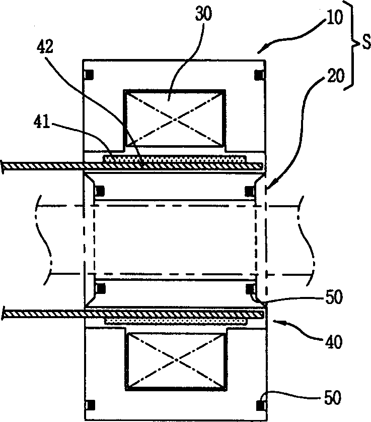
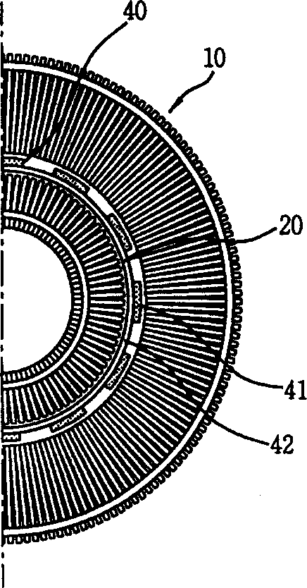
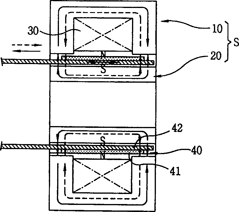
[0051] see Figure 5 , Image 6 As shown, the laminated iron core fixing structure of the reciprocating motor of the present invention consists of the following structures: a coil barrel 200 , a terminal portion 300 , a first laminated iron core 400 and a second laminated iron core 500 . The coil barrel 200 is wound with the coil 100 inside the ring; the terminal part 300 is arranged on one side of the coil barrel 200, and tr...


PUM


Abstract

This invention relates to a reciprocal movement electric machine improved stacked core fixing structure including iron core, coil, and fixing rings, the said coil tube is an insulator with coil woundin it, the terminal part and the coil tube formed into one integral unit with external power supply turned-on to the coil, a first and a second layers of stacked iron cores are stacked bodies, among which the first one is formed by multiple silicon-steel sheets in specific sheet shape and the second one is plug into inside or outside of the first one kept at a certain distance, the insertion slots are set up on the first and second stacked iron cores in concentric circles, the fixing ring is pressed into the slot, and its inlet side section is narrower than the central section.

Description

technical field [0001] The invention relates to a motor with an improved motor iron core fixing structure in the field of motors, in particular to a laminated iron core that can not only form a cylindrical laminated body by laminating thin silicon steel sheets with a specific shape in a radial manner It is easy to fix and has a laminated iron core fixing structure of a reciprocating motor with accurate assembly dimensions. Background technique [0002] A general motor is a machine that converts electrical energy into kinetic energy. Motors can be divided into many types such as rotary motors and reciprocating motors. The rotary motor is a motor that converts electrical energy into rotational motion; the above-mentioned reciprocating motor is a motor that converts electrical energy into linear reciprocating motion. [0003] Motors are used as a power source in a wide range of fields. This is especially true for home appliances; for example, refrigerators, air conditioners,...

Claims


Application Information

Patent Timeline
Patent Type & Authority Applications(China)
IPC IPC(8): H02K1/12H02K33/18
Inventor 李东远李树源郑圆铉
Owner LG ELECTRONICS (TIANJIN) APPLIANCES CO LTD
Why Eureka
Try Eureka