Signal and power supply integrated mode switching structure and method thereof

A mode switching and signal technology, applied in the field of signal switching, can solve the problems of poor contact, large deviation of assembly size, occupying space, etc., and achieve the effect of accurate switching time demarcation point, accurate assembly size and small space occupation

Inactive Publication Date: 2007-12-12
ALTEK CORP
View PDF2 Cites 0 Cited by
  • Summary
  • Abstract
  • Description
  • Claims
  • Application Information

AI Technical Summary

Problems solved by technology

[0002] The function mode switch (Mode switch) of the existing digital camera is independent and can be operated by several signal switches, and the power switch operation of the digital camera is performed by another power switch, and the power signal and function cannot be combined. The switch of the signal is integrated into one, so a power switch must be provided next to the function mode switch, so it has the following defects: 1. Since several signal switches are used to form different function option signals, the usable function interface is limited. Due to the limitation of the mechanism space, it is not easy to increase the number of new modes; 2. Since the switches of the function signal and the power signal are separated independently, it takes up space and requires more mode control chips, resulting in high cost, and the deviation of the assembly size is also relatively large. 3. It is not only difficult to design the mechanism, but also may malfunction
[0003] It is known that there is another traditional mechanism circuit method, which is to control each group of signals by contacting the circuit board with a set of brush shrapnel, but it still needs to pull another set of power switch signals to operate, and the control and circuit of the brush shrapnel The contact surface requirements of the pads are very strict. If there is a mistake, the contact failure rate of the brush shrapnel and the welding pad will increase, so there is a lack of easy assembly; moreover, the brush shrapnel is easy to be deformed during packaging, assembly or heavy work , resulting in poor contact; in addition, corrosion problems are likely to cause poor contact, and in order to prevent corrosion, the contact surface of the circuit board pad must be gold-plated, resulting in increased cost; and the brush shrapnel must be locked with the circuit board so that The assembly method is limited, and various problems make this traditional mechanism circuit method more uneconomical

Method used


Image

  • Signal and power supply integrated mode switching structure and method thereof
  • Signal and power supply integrated mode switching structure and method thereof
  • Signal and power supply integrated mode switching structure and method thereof

Examples


Embodiment Construction

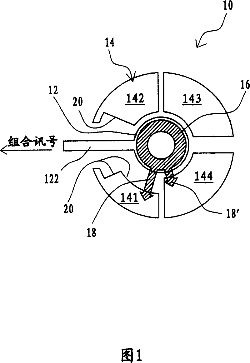
[0032] In the present invention, the function option signal and the power switch signal are combined to act on the same switch, so that one switch can simultaneously provide the dual functions of the power switch and the function option switch.

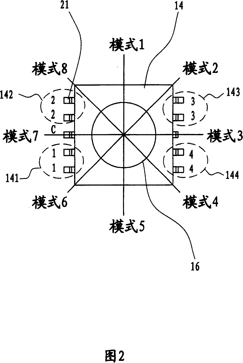
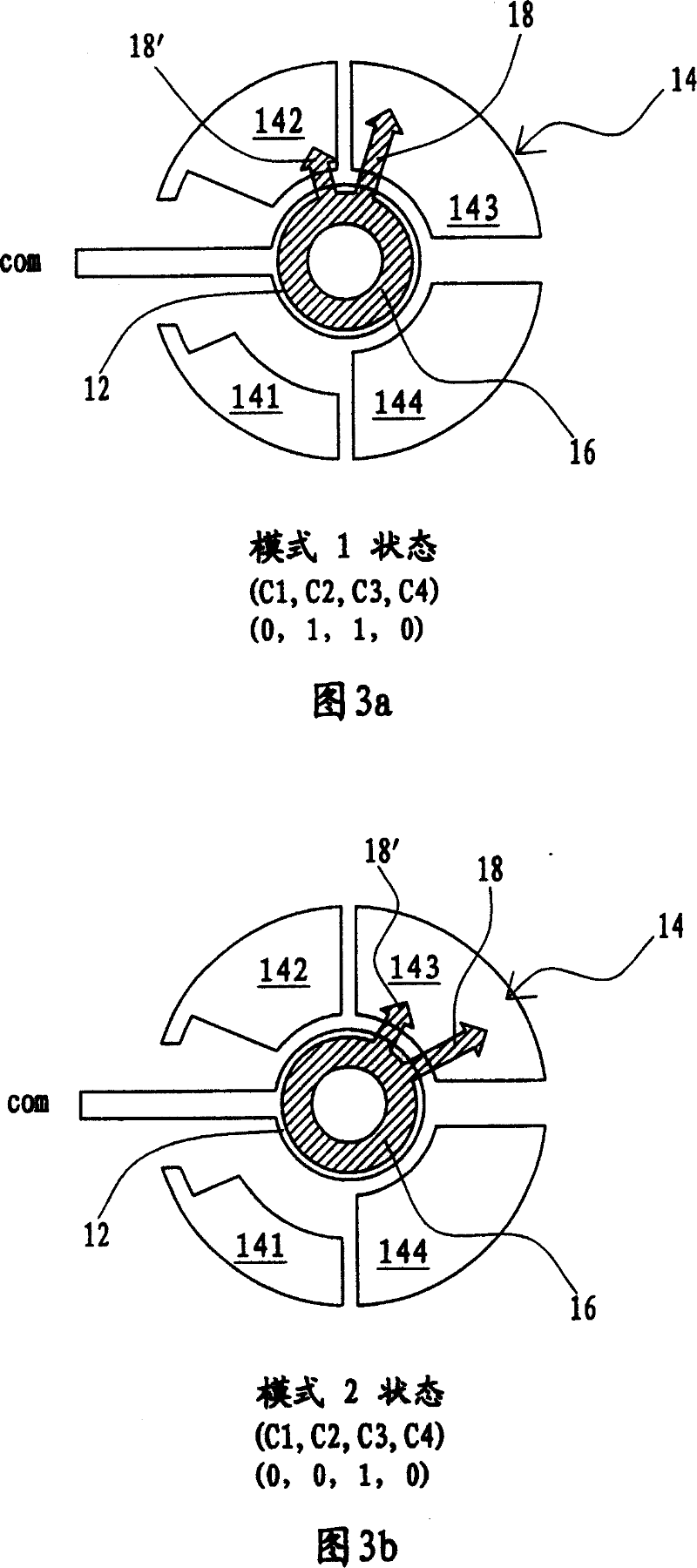
[0033] As shown in FIG. 1 , it is a structural diagram of an embodiment of the present invention, which will be used to describe in detail the circuit structure of the present invention and the signal layout method for combining signals and power in the same switch. The mode switching structure 10 of the present invention includes a signal output contact 12, which is connected to a line 122 and extends outward; a mode configuration circuit 14 is arranged around the signal output contact 12, and it consists of four conductive contacts (Pad) 141 . Extend between the conductive contacts 141 and 142; there is also a rotatable mode switcher 16, which is provided with two conductive pins 18, 18', one long and one short, to bridge the signal...


PUM


Abstract

A mode switching over unit combining signal and power in one body is featured as setting multiple conductive contacts around a signal contact, forming mode configuration circuit with different mode by utilizing said conductive contacts to form combined signal , defining one mode as power switch signal and the rest modes as function selecting signal , using rotary switcher pin to connect signal output contact and mode configuration circuit , triggering a combined signal for outputting by moving said pin to be different angle to contact with conductive contact of mode configuration circuit.

Description

technical field [0001] The invention relates to a signal switching technology, in particular to a mode switching structure and method in which signal and power are integrated. Background technique [0002] The function mode switch (Mode switch) of the existing digital camera is independent and can be operated by several signal switches, and the power switch operation of the digital camera is performed by another power switch, and the power signal and function cannot be combined. The switch of the signal is integrated into one, so a power switch must be provided next to the function mode switch, so it has the following defects: 1. Since several signal switches are used to form different function option signals, the usable function interface is limited. Due to the limitation of the mechanism space, it is not easy to increase the number of new modes; 2. Since the switches of the function signal and the power signal are separated independently, it takes up space and requires mor...

Claims


Application Information

Patent Timeline
IPC IPC(8): H01H19/58H01H21/18
Inventor 萧舜元朱峻成
Owner ALTEK CORP
Why Eureka
Try Eureka