Eureka AIR delivers breakthrough ideas for toughest innovation challenges, trusted by R&D personnel around the world.

A dual-motor power synthesis device for electric vehicle drive

A technology for power synthesis and electric vehicles, which is applied in the layout of electric power units, power units, and the cooling combination of power units, and can solve problems such as inconvenient control.

Active Publication Date: 2021-05-04
郑酉香
View PDF9 Cites 0 Cited by
  • Summary
  • Abstract
  • Description
  • Claims
  • Application Information

AI Technical Summary

Problems solved by technology

[0009] The purpose of the present invention is to provide a dual-motor power synthesis device for driving electric vehicles, so as to solve the problem that it is inconvenient to control the speed change and steering in the above-mentioned background technology

Method used


Image

  • A dual-motor power synthesis device for electric vehicle drive
  • A dual-motor power synthesis device for electric vehicle drive
  • A dual-motor power synthesis device for electric vehicle drive

Examples


Embodiment 1

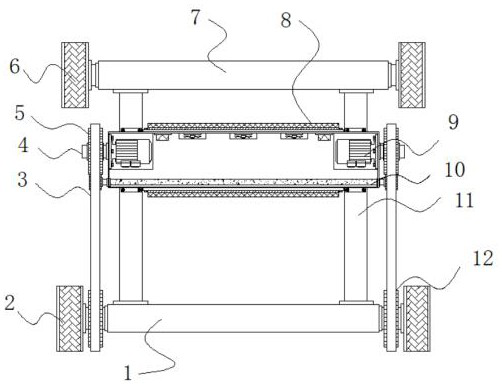
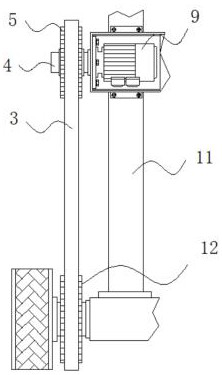
[0034] Example 1: See Figure 1-6 , a dual-motor power synthesis device for driving an electric vehicle, comprising a front pole 1 and a front wheel 2, two groups of front wheels 2 are fixedly connected to both sides of the front pole 1, and a rear pole 7 is arranged on the top of the front pole 1, Two groups of rear wheels 6 are fixedly connected to both sides of the rear bar 7, two groups of connecting rods 11 are fixedly connected between the front rod 1 and the rear rod 7, and one end of the connecting rod 11 is fixedly connected to a shell 17, the top of the shell 17 and the The bottom end is fixedly connected with a heat dissipation mechanism 8, and the bottom end inside the casing 17 is provided with an energy-saving structure 10, and four sets of fixing pieces 13 are arranged on both sides of the top and bottom of the casing 17, and two sets of fixing pieces 13 are fixedly connected on both sides of one end of the fixing piece 13. Bolts 14, wear-reducing structures 16 ...

Embodiment 2

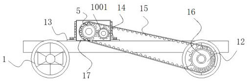
[0036] Embodiment 2: Four sets of fixing pieces 13 are arranged on both sides of the top and bottom of the housing 17; the fixing bolts 14 penetrate one end of the fixing piece 13 and are fixedly connected with the connecting rod 11; specifically, as figure 1 and figure 2 As shown, the electric vehicle consumes a large amount of electric energy when in use, which increases the cost of use. When the vehicle does not need a large amount of electric energy to drive, it only needs to drive the variable speed motor 9 on one side, and the motor drives the first gear 5 to rotate. , the second gear 1001 that meshes with the first gear 5 also rotates, and then the second gear 1001 drives the gear on the other side to rotate to drive the vehicle to drive normally, which reduces energy consumption and saves a lot of electric energy. Reduced cost consumption.

Embodiment 3

[0037] Embodiment 3: the heat dissipation mechanism 8 is made up of a heat dissipation gasket 801, a heat dissipation box 802, a heat dissipation hole 803, a blade 804 and a heat dissipation net plate 805, and the heat dissipation gasket 801 is fixedly connected to the top and bottom of the shell 17, and the heat dissipation gasket 801 The top is fixedly connected with a heat dissipation mesh plate 805, and the top inside the housing 17 is fixedly connected with three groups of heat dissipation boxes 802. The bottom of the heat dissipation box 802 is provided with a heat dissipation hole 803, and the inside of the heat dissipation box 802 is fixedly connected with a blade 804. The model of the blade 804 for DP200A;

[0038] The heat dissipation mesh plate 805 and the heat dissipation gasket 801 are on the same level; specifically, as figure 1 and Figure 4 As shown, the device will generate a large amount of heat energy under high-intensity use. The temperature sensor install...


PUM


Abstract

The invention discloses a dual-motor power synthesis device for driving an electric vehicle, specifically relates to the technical field of electric vehicle transmission, and comprises a front rod and a front wheel. Two sets of front wheels are fixedly connected to both sides of the front rod. The present invention is provided with crawler belt, first bearing, first gear, variable speed motor and third gear, and when the device is started, it uses variable speed motor, first gear and third gear to drive the rolling of the front wheel and rear wheel, and needs to change speed At the same time, only need to control the two groups of variable speed motors to synchronously shift to a certain value, and the speed change of the vehicle can be realized. The variable-speed motor on one side can be turned off, and only the variable-speed motor on the other side can be turned on. The whole process can be completed by controlling the motor. It is simple and easy to operate, and solves the inconvenience of variable speed and steering in the existing dual-motor synthesis device. question.

Description

technical field [0001] The invention relates to the technical field of electric vehicle transmission, in particular to a dual-motor power synthesis device for driving electric vehicles. Background technique [0002] With the development of science and technology, more and more motor vehicles are widely used, and the emission of vehicle exhaust has aggravated the deterioration of the environment. Now more and more attention is paid to the development of new energy electric vehicles. Electric vehicles have achieved zero fuel consumption, zero emissions, and effective To improve the problem of environmental pollution, the driving of electric vehicles requires the use of dual-motor power synthesis devices, and the existing dual-motor power synthesis devices still have some shortcomings that need to be improved. [0003] In the process of realizing the present invention, the inventors have found that at least the following problems in the prior art have not been resolved: [000...

Claims


Application Information

Patent Timeline
Patent Type & Authority Patents(China)
IPC IPC(8): B60K1/02B60K17/08B60K11/00B62D11/04
CPCB60K1/02B60K11/00B60K17/08B62D11/04
Inventor 郑酉香
Owner 郑酉香
Why Eureka
Eureka Blog
Learn More