Intelligent fine adjustment system for ballastless track plate
A technology of ballastless track and track slab, which is applied in the direction of track, track laying, track maintenance, etc. It can solve the problem of low efficiency of track slab fine adjustment, and achieve the effects of weight reduction, convenient movement and portability
- Summary
- Abstract
- Description
- Claims
- Application Information
AI Technical Summary
Problems solved by technology
Method used
Image
Examples
Embodiment 1
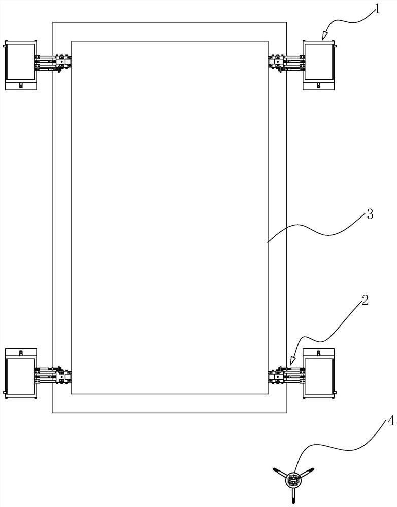
[0044] refer to figure 1 , this embodiment discloses an intelligent fine-tuning system for a ballastless track slab, including a measuring device 4 for measuring the position data of a ballastless track slab 3, four fine-tuning claws 2, and four for driving fine-tuning Adjustment mechanism 1 for jaws 2. The measurement device 4 adopts a total station, and a fine-tuning frame is placed on the corresponding rail platform, and the total station is erected to complete the installation of the total station. Four corners of the ballastless track slab 3 are respectively provided with a fine adjustment claw 2, and each fine adjustment claw 2 is respectively connected with an adjustment mechanism.
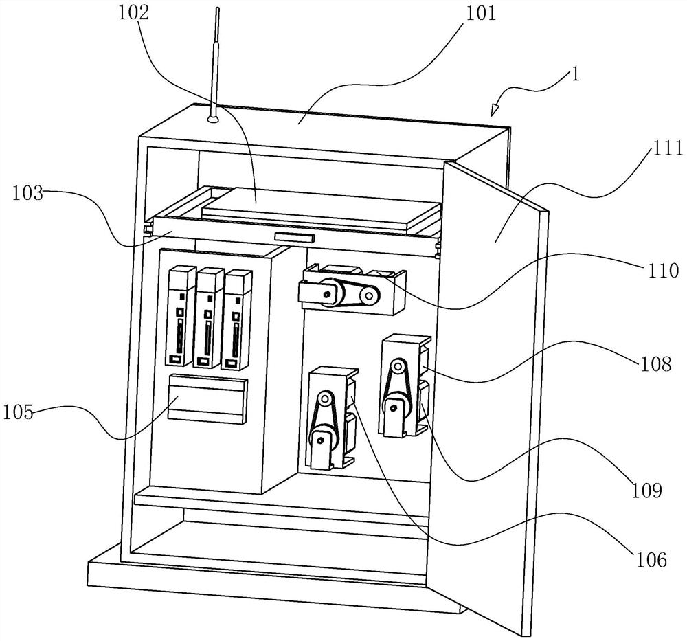
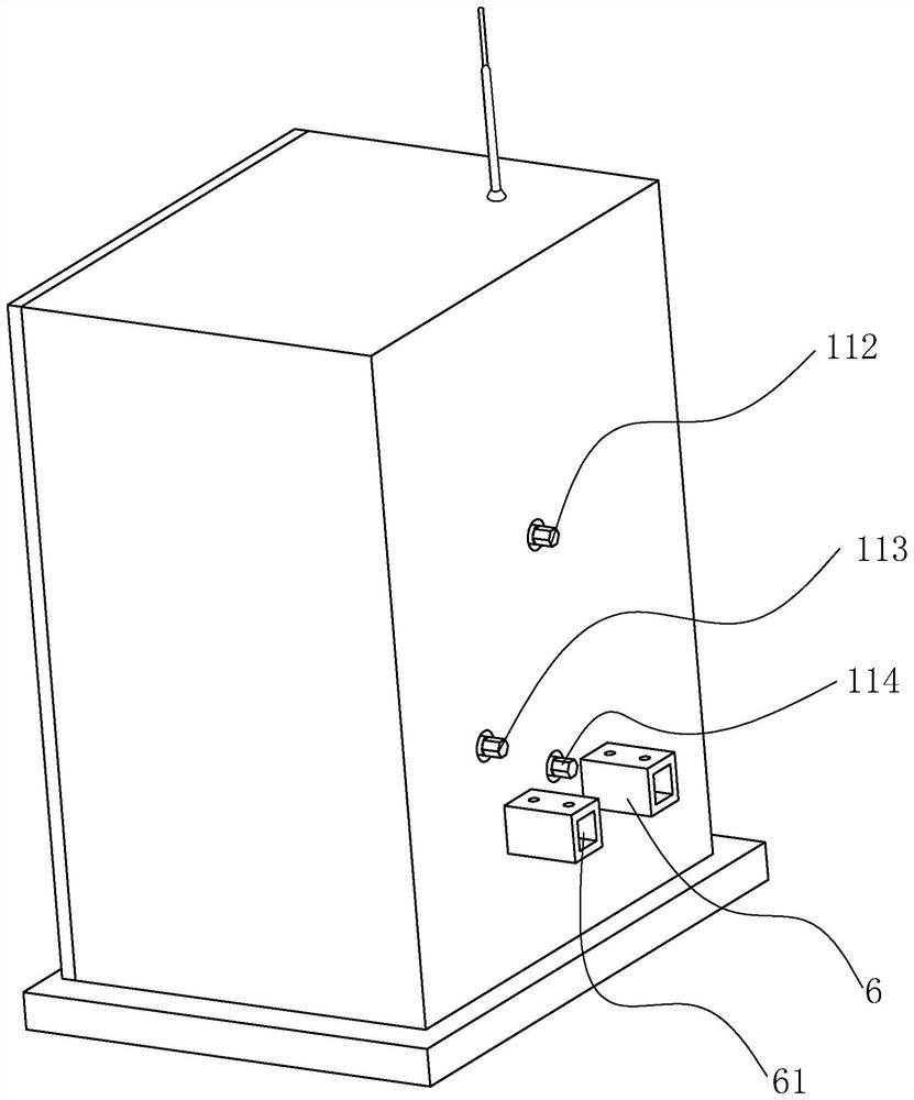
[0045] refer to figure 2 with image 3 , the adjustment mechanism includes a box body 101, and a box door 111 is also arranged on the box body 101. The box door 111 is arranged on the side of the box body 101 away from the fine adjustment claw 2, that is, the back side of the box body 1...
Embodiment 2
[0061] refer to Figure 7 with Figure 8 , the rest of this embodiment is the same as Embodiment 1, the difference is that in order to make the fine adjustment claw 2 itself have a certain position deviation compensation ability when adjusting, the bottom of the Z-direction screw rod 202 is set as a hemisphere Shaped connecting portion 225, on the X-direction slider 216, a receiving groove matching the hemispherical connecting portion 225 is provided, the connecting portion 225 is set in the receiving groove, and the connecting portion 225 is pressed into the In the storage slot, the connecting portion 225 cannot escape upwards from the storage slot. The pressing plate 224 is fixed to the X-direction sliding block 216 through locking screws 223 , and the connecting portion 225 is pressed into the receiving groove of the X-direction sliding block 216 . The Z-direction screw rod 202 can rotate on the X-direction slider 216 , and can also swing at a certain angle on the X-direc...
Embodiment 3
[0065] refer to Figure 10, the rest of this embodiment is the same as Embodiment 2, the difference is that in order to enable the adjustment mechanism 1 to be positioned and connected with the fine adjustment claw 2 more quickly, the box body 101 is arranged on a base 117, and the base 117 It is connected with the box body 101 through a lifting mechanism. In this embodiment, the lifting mechanism includes a fork 118 and an oil cylinder 104 . A lockable universal wheel 116 is arranged at the bottom of the base 117 , and a push handle 115 is also arranged on the base 117 .
[0066] When it is necessary to install the adjustment mechanism 1, push the adjustment mechanism 1 to the corresponding position, then adjust the oil cylinder 104, so that the box body 101 rises to a suitable height, and connect the four adjustment mechanisms 1 through the floating cross coupling 5 and fine adjustment The claw 2 is connected, and then inserted into the installation groove 61 on the positio...
PUM
 Abstract
Description
Claims
Application Information
 - R&D
- Intellectual Property
- Life Sciences
- Materials
- Tech Scout
- Unparalleled Data Quality
- Higher Quality Content
- 60% Fewer Hallucinations
Browse by: Latest US Patents, China's latest patents, Technical Efficacy Thesaurus, Application Domain, Technology Topic, Popular Technical Reports.
© 2025 PatSnap. All rights reserved.Legal|Privacy policy|Modern Slavery Act Transparency Statement|Sitemap|About US| Contact US: help@patsnap.com


