Vibration drainage device for concrete pouring

A technology for concrete and moving blocks, which is applied in construction, building structure, construction material processing, etc., can solve problems such as difficulty in accurately controlling the insertion depth of vibrating rods, poor quality of plasticized concrete parts, and uneven concrete vibration. , to increase quality, eliminate seams, and improve practicality

Active Publication Date: 2021-09-28
中国水利水电第七工程局有限公司
View PDF5 Cites 0 Cited by
  • Summary
  • Abstract
  • Description
  • Claims
  • Application Information

AI Technical Summary

Problems solved by technology

[0003] The existing vibration drainage device for concrete pouring is mainly composed of a vibration motor, a flexible shaft tube, a vibrating rod, etc. When in use, the worker holds the vibrating rod and inserts it into the concrete poured in the mold, and then the vibrating rod vibrates and acts on the concrete. The concrete is compacted. However, it is difficult for workers to strictly follow the construction requirements of fast insertion and slow extraction, uniform insertion points, point-by-point movement, sequential progress, and no omissions in the process of manually operating the vibrating rod. There is a problem of uneven concrete vibration. Moreover, it is difficult for workers to accurately control the moving distance of the vibrating rod to be less than 1.5 times the radius of action of the vibrating rod, which may easily lead to missing problems. 50 mm concrete surface to eliminate the joint between the two layers, but it is difficult for workers to accurately control the insertion depth of the vibrating rod, resulting in poor quality of concrete plasticized moldings poured in layers, so it is urgent to design a concrete Vibration drainage device for pouring

Method used


Image

  • Vibration drainage device for concrete pouring
  • Vibration drainage device for concrete pouring
  • Vibration drainage device for concrete pouring

Examples


Embodiment Construction

[0033] The technical solutions in the embodiments of the present invention will be clearly and completely described below in conjunction with the accompanying drawings in the embodiments of the present invention; obviously, the described embodiments are only some embodiments of the present invention; rather than all embodiments. Based on the embodiments of the present invention; all other embodiments obtained by persons of ordinary skill in the art without creative work; all belong to the protection scope of the present invention.

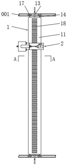
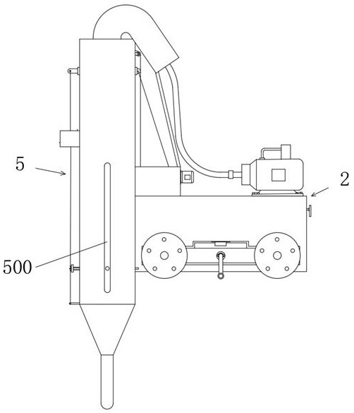
[0034] see Figure 1-11 , a vibration drainage device for concrete pouring, comprising a U-shaped walking track 001, and a transverse traveling mechanism 1 is arranged on the U-shaped walking track 001.

[0035] The horizontal running mechanism 1 includes a walking flat tube 11, on which the running flat tube 11 is provided with a longitudinal running mechanism 2, on which a driving tube 12 is movably inserted, and the end of the driving tube 12 ex...


PUM


Abstract

The invention discloses a vibration drainage device for concrete pouring, which comprises a U-shaped walking track, and a transverse walking mechanism is arranged on the U-shaped walking track; through a transverse walking mechanism, a longitudinal walking mechanism, a linkage device, a trigger device, a guiding device, The cooperation of the depth limit device, the automatic control device and the conductive device enables the longitudinal traveling mechanism to automatically move at a fixed distance in the vertical direction. The construction requirements of moving, proceeding in sequence, and not being missed improve the quality of concrete plasticized moldings. The depth of the vibrating rod inserted into the concrete is limited by the depth-limiting device to ensure that the bottom end of the vibrating rod is inserted into the concrete when the upper layer is vibrated. The concrete surface of the next layer is 50 millimeters, which increases the quality of the concrete plasticized molded parts poured in layers, and improves the practicability of the vibration drainage device for pouring concrete.

Description

technical field [0001] The invention relates to the field of concrete pouring equipment, in particular to a vibration drainage device for concrete pouring. Background technique [0002] Concrete refers to the collective name of engineering composite materials that use cementitious materials to cement aggregates into a whole. The term concrete usually refers to the use of cement as cementitious material, sand and stone as aggregates, and water in a certain proportion. The cement concrete obtained by mixing is also called ordinary concrete. Concrete pouring refers to the process of pouring concrete into the mold until the concrete is plasticized. The purpose of drainage is to discharge the air bubbles inside the concrete and fill the cavity where the air bubbles are with concrete, and then tamp the concrete, so as to improve the quality of the plasticized concrete moldings. [0003] The existing vibration drainage device for concrete pouring is mainly composed of a vibration ...

Claims


Application Information

Patent Timeline
Patent Type & Authority Patents(China)
IPC IPC(8): E04G21/08
CPCE04G21/08
Inventor 罗冉张光辉龚兵文邱海龙薛惠江
Owner 中国水利水电第七工程局有限公司
Why Eureka
Try Eureka