
A powder conductivity test equipment

A technology for testing equipment and conductivity, which is applied to parts of electrical measuring instruments, measuring devices, and measuring electrical variables. The effect of measurement accuracy

Inactive Publication Date: 2020-06-02
ZHEJIANG FOREVER NEW ENERGY TECH CO LTD +1
View PDF11 Cites 0 Cited by
  • Summary
  • Abstract
  • Description
  • Claims
  • Application Information

AI Technical Summary

Problems solved by technology

[0005] In view of the above-mentioned problems in the prior art, the object of the present invention is to provide a powder conductivity testing device, which is used to solve the defects of large measurement errors and low measurement accuracy existing in the existing powder conductivity testing equipment

Method used


Image

  • A powder conductivity test equipment
  • A powder conductivity test equipment
  • A powder conductivity test equipment

Examples


Embodiment 1

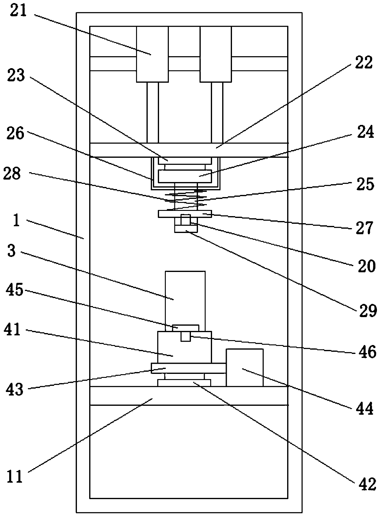
[0034] This embodiment provides a powder conductivity testing device. By designing a structure capable of driving the material tube to vibrate, the powder in the material tube is vibrated evenly, thereby improving the uniformity of the powder density and improving the measurement accuracy.

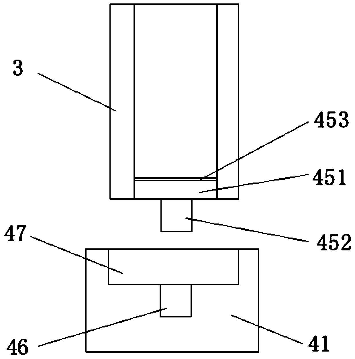
[0035] The powder conductivity testing equipment provided in this embodiment includes a bracket 1, a pressure applying mechanism, a material pipe 3 and a pressure bearing mechanism, the pressure bearing mechanism is arranged at the lower part of the bracket 1, and the material pipe 3 is installed on the bearing On the pressure mechanism, the pressure applying mechanism is arranged on the upper part of the support 1, the material pipe 3 is used to accommodate the powder whose conductivity is to be tested, and the pressure applying mechanism is used to apply a test pressure to the material pipe 3.

[0036] Wherein, the support 1 is a frame structure, including an upper connection plate, a low...

Embodiment 2

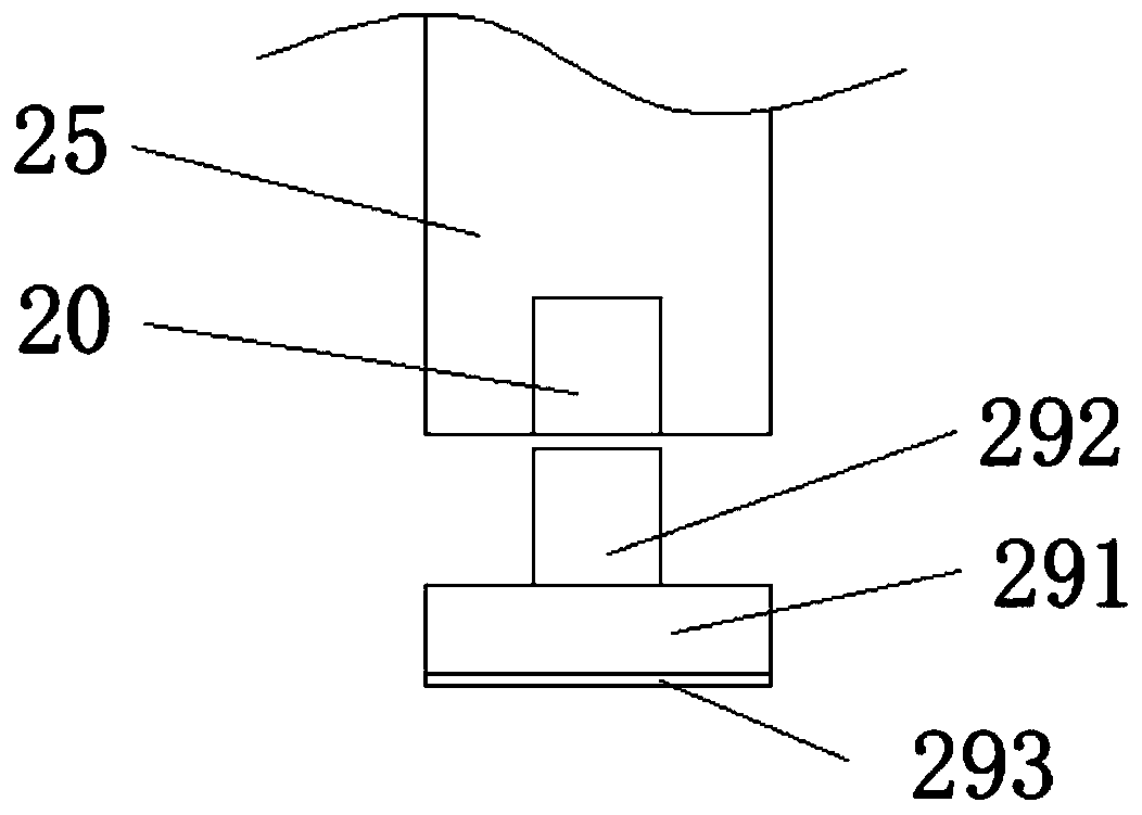
[0046] This embodiment provides a powder conductivity testing device. On the one hand, the powder in the material tube is vibrated evenly by designing a structure that drives the material to vibrate, improving the uniformity of the powder density and improving the measurement accuracy; on the other hand, in conjunction with The deformation layer is set on the upper conductive pressure head and the lower conductive pressure head in contact with the powder, and the contact area between the upper conductive pressure head and the lower conductive pressure head and the powder is increased through the deformation layer, and the contact area between the upper conductive pressure head and the lower conductive pressure head and the powder is improved. The contact effect can avoid measurement errors caused by poor contact, thereby further improving the measurement accuracy.

[0047] The powder conductivity testing equipment provided in this embodiment includes a bracket 1, a pressure app...


PUM


Abstract

The invention relates to a detection instrument and particularly relates to a powder conductivity test device, which comprises a support, a pressing mechanism, a material tube and a pressure bearing mechanism, wherein the pressure bearing mechanism is arranged at the lower part of the support; the material tube is arranged on the pressure bearing mechanism; the pressing mechanism is arranged at the upper part of the support; the material tube is used for accommodating powder with conductivity to be tested; the pressing mechanism is used for applying test pressure to the material tube; the pressure bearing mechanism comprises a material table, a first cushion, a vibrating sheet and a first driver; the vibrating sheet can drive the material table and the material tube to vibrate under driving of the first driver; the pressing mechanism comprises a second driver, a sliding cross rod, a second cushion, a pressure sensor and a conductive pressing rod; and the sliding cross rod can drive theconductive pressing rod to move towards the material tube under driving of the second driver. Thus, the powder conductivity measurement precision can be improved.

Description

technical field [0001] The invention relates to a detection instrument, in particular to a powder conductivity test device. Background technique [0002] In the production process of lithium batteries, both the positive and negative electrodes are made of powder. Therefore, in the process of developing lithium batteries, it is often necessary to test the performance of various powders. Among them, the conductivity of the positive electrode material powder is an important factor affecting the battery rate. In the process of developing the battery, it is necessary to conduct various tests on the conductivity of the positive electrode material powder. [0003] When the compaction density of the positive electrode material is different, its electrical conductivity is also different. The patent application number CN201220082173.9 discloses a powder resistivity test bench, which can be used with a four-probe tester to test synchronously while applying pressure, so as to facilita...

Claims


Application Information

Patent Timeline
Patent Type & Authority Patents(China)
IPC IPC(8): G01R27/02G01R1/04
CPCG01R1/0416G01R27/02
Inventor 鲍添增陈昌平刘金辉尹佳
Owner ZHEJIANG FOREVER NEW ENERGY TECH CO LTD
Learn More