Shakeout device used for water faucet production

A sand falling device and faucet technology, applied in the cleaning/processing machinery of casting materials, casting molding equipment, manufacturing tools, etc., can solve the problem that debris is easy to pollute the working environment, etc., to promote rapid falling and stable vibration Effect

Pending Publication Date: 2021-05-11
临澧嘉宸铸业有限公司
View PDF0 Cites 0 Cited by
  • Summary
  • Abstract
  • Description
  • Claims
  • Application Information

AI Technical Summary

Problems solved by technology

[0007] The purpose of the present invention is to provide a kind of shakeout device that is used for faucet production, to solve the problem that the debris that shakes off in the above-mentioned background technology is easy to pollute the working environment

Method used


Image

  • Shakeout device used for water faucet production
  • Shakeout device used for water faucet production
  • Shakeout device used for water faucet production

Examples


Embodiment 1

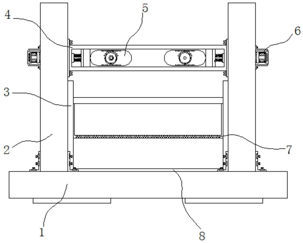
[0025] Example 1: See Figure 1-4 , a sand shakeout device for faucet production, comprising a base 1, a side plate 2 and a housing 4, the two sides of the top of the base 1 are respectively fixedly connected with side plates 2, and the inside of one side of the side plate 2 is provided with an empty groove 3. A hidden chamber 12 is provided at the top of the cavity 3, a housing 4 is fixedly connected to the top between one side of the side plate 2, and a main board 10 is provided between one end of the housing 4, and the main board 10 and the housing 4 A vibrating mechanism 5 is arranged between one end of the main board 10, a clamping structure 9 is arranged inside the main board 10, and a screening mechanism is arranged between the empty groove 3 and the hidden chamber 12;

[0026] see Figure 1-4 , a shakeout device for faucet production also includes that the screening mechanism includes a second motor 6, and the second motor 6 is fixedly connected to the top of one side...

Embodiment 2

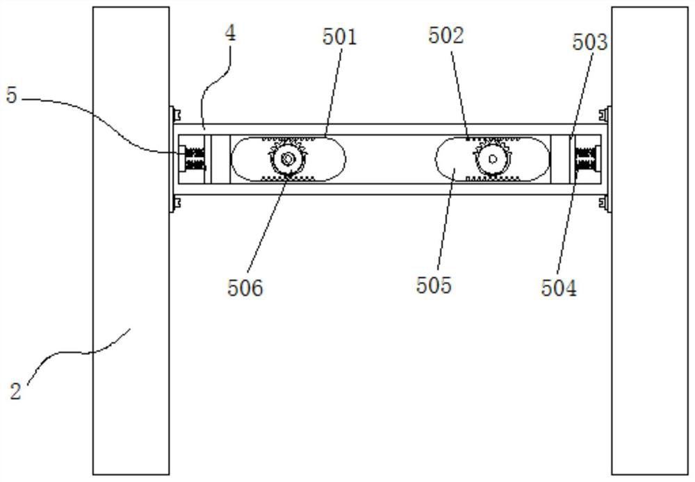
[0028] Embodiment 2: Vibration mechanism 5 is made up of slide plate 501, gear block 502, cushion 503, buffer spring 504, chute 505, guide gear 506 and first motor 507, and slide plate 501 is slidably connected between the both sides of housing 4 inside Between the two sides of the sliding plate 501 are respectively provided with chute 505, and the top and bottom of the chute 505 are respectively fixedly connected with a plurality of groups of tooth blocks 502, and a guide gear 506 is arranged between the tooth blocks 502, and the guide gear 506 One end of the housing 4 is fixedly connected to a first motor 507. The model of the first motor 507 can be ECMA-C20401ES. The buffer springs 504 are fixedly connected to both sides of the housing 4. The fixed connection has a cushion 503;

[0029] The diameter of guide gear 506 is less than the inner diameter of chute 505, and chute 505 is symmetrically distributed about the vertical center line of slide plate 501;

[0030] Specifica...

Embodiment 3

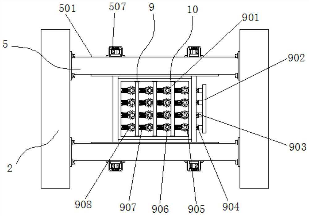
[0031]Embodiment 3: the clamping structure 9 is made up of fixed rod 901, pull plate 902, sliding sleeve 903, fastening bolt 904, right clamping block 905, drawing rod 906, tension spring 907 and left clamping block 908, and fixed rod 901 is respectively Fixedly connected between the two ends inside the main board 10, the fixed rod 901 and one side of the main board 10 are respectively fixedly connected with a right clamping block 905, and a drawing rod 906 is movably connected between the right clamping block 905 and one side of the main board 10, One end on one side of the drawing rod 906 is fixedly connected with a pull plate 902, and the sliding sleeves 903 are respectively fixedly connected to one side of the main board 10. A fastening bolt 904 is movably connected between the sliding sleeve 903 and the drawing rod 906, and the fixed rod 901 and The other side of the main board 10 is fixedly connected with multiple sets of tension springs 907, and one side of the tension s...


PUM


Abstract

The invention discloses a shakeout device used for water faucet production, and particularly relates to the technical field of water faucet machining device. The shakeout device comprises a base, side plates and a shell body, the side plates are fixedly connected to the two sides of the top end of the base correspondingly, an empty groove is formed in the interior of one side of each side plate, a hidden cavity is formed in the top end of the interior of each empty groove, the shell body is fixedly connected to the top end between one sides of the side plates, a main board is arranged between one end of the shell body, a vibration mechanism is arranged between the main board and one end of the shell body, and a clamping structure is arranged in the interior of the main board. According to the shakeout device, the vibration mechanism is arranged between the main board and one end of the shell body, a first motor is started, in cooperation with tooth blocks, guide gears at respective output ends are driven to slide left and right in the interiors of sliding grooves in the same direction, after a cushion is connected, a buffer spring dissipates impact force and plays a vibration role at the same time, sand slag can be promoted to rapidly fall off, and a machine body is not damaged.

Description

technical field [0001] The invention relates to the technical field of faucet processing devices, in particular to a sand shakeout device for faucet production. Background technique [0002] At present, almost every household installs and uses water pipes. In order to avoid water leakage, the requirements for faucets are getting higher and higher. When processing and finalizing this product, sand cores are required as its internal model. After positioning, it still needs to be heated and removed, but it is inevitable. There is debris remaining inside the faucet, so there is an urgent need for an efficient and useful shakeout device. [0003] In the process of realizing the present invention, the inventor finds that there are at least the following problems in the prior art that have not been solved: [0004] (1) The traditional shakeout device used for faucet production is not equipped with a structure for screening and collecting debris dust, which is not convenient for so...

Claims


Application Information

Patent Timeline
IPC IPC(8): B22D31/00B22C5/06
CPCB22C5/06B22D31/00
Inventor 乔玉和
Owner 临澧嘉宸铸业有限公司
Why Eureka
Try Eureka