Interlayer pressurizing pipeline sleeve structure of liquefied natural gas cylinder and assembling method thereof

A technology of liquefied natural gas and pressurized pipes, which is applied in the direction of pipes/pipe joints/fittings, pipes, mechanical equipment, etc. It can solve the problems of small interlayer space of gas cylinders, loss of vacuum of gas cylinders, unusable service life, etc., and achieve crack failure , local stress concentration is small, and the effect of reducing the overall force

Inactive Publication Date: 2021-01-05
XIAN DESEN NEW ENERGY EQUIP
View PDF5 Cites 0 Cited by
  • Summary
  • Abstract
  • Description
  • Claims
  • Application Information

AI Technical Summary

Problems solved by technology

The interlayer space of the gas cylinder is small, and the vehicle is subjected to fatigue loads during driving. The structural design of the interlayer booster tube should not only match the rigidity of the overall structure of the gas cylinder, but also meet the performance requirements, and at the same time, it should not be too large. Therefore, the structure of the sandwich booster tube Design is very important. At present, there are often cracks and failures in the body of the self-pressurized gas cylinder interlayer pressurized tube or the heat-affected zone of the welded joint, resulting in the loss of vacuum of the gas cylinder, and the end of life cannot be used.

Method used


Image

  • Interlayer pressurizing pipeline sleeve structure of liquefied natural gas cylinder and assembling method thereof
  • Interlayer pressurizing pipeline sleeve structure of liquefied natural gas cylinder and assembling method thereof

Examples


Embodiment Construction

[0020] The above and other technical features and advantages of the present invention will be described in more detail below in conjunction with the accompanying drawings.

[0021] In describing the present invention, it should be understood that the terms "center", "longitudinal", "transverse", "length", "width", "thickness", "upper", "lower", "front", " Back", "Left", "Right", "Vertical", "Horizontal", "Top", "Bottom", "Inner", "Outer", "Clockwise", "Counterclockwise", "Axial", The orientations or positional relationships indicated by "radial", "circumferential", etc. are based on the orientations or positional relationships shown in the drawings, and are only for the convenience of describing the present invention, rather than indicating or implying that the referred device or element must have a specific orientation, are constructed and operate in a particular orientation and therefore are not to be construed as limiting the invention.

[0022] In addition, the terms "fir...


PUM


Abstract

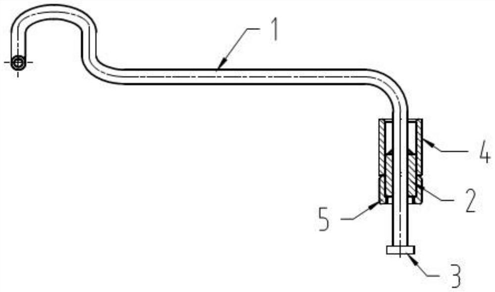
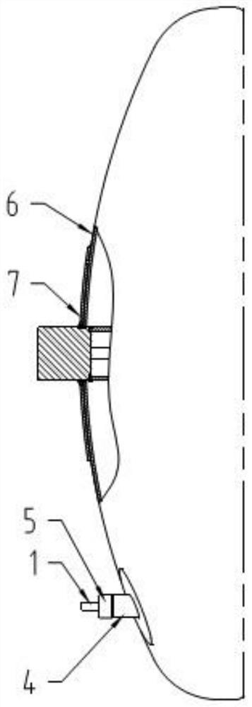
The invention relates to the technical field of automobile liquefied natural gas cylinders, in particular to an interlayer pressurizing pipeline sleeve structure of a liquefied natural gas cylinder and an assembling method thereof. The structure comprises an interlayer pressurizing pipe, an outer container front end socket, an outer front reinforcing plate, an inner sleeve, a first outer sleeve and a second outer sleeve, wherein the inner sleeve is fixedly arranged at the position of a front straight pipe section of the interlayer pressurizing pipe in a sleeving mode; the first outer sleeve and the second outer sleeve are sequentially and fixedly arranged outside the inner sleeve from front to back in the sleeving mode; the second outer sleeve penetrates through the outer container front end socket to weld and fix, and a front end opening of the interlayer pressurizing pipe is located outside the outer container front end socket; the outer front reinforcing plate is welded on the outersurface of the middle of the outer container front end socket; and the outer container front end socket and the outer front reinforcing plate are both 4 mm in wall thickness. The interlayer pressurizing pipeline sleeve structure reduces overall stress of the interlayer pressurizing pipeline structure, and solves the problem of crack failure of a self-pressurizing gas cylinder interlayer pressurizing pipe body or a welding joint heat affected zone.

Description

technical field [0001] The invention relates to the technical field of liquefied natural gas cylinders for vehicles, in particular to a casing structure of a liquefied natural gas cylinder interlayer pressurization pipeline and an assembly method thereof. Background technique [0002] As a low-temperature adiabatic pressure vessel, the liquefied natural gas cylinder for vehicles is designed with a double-layer vacuum structure. In the four zones divided by vacuum, after the LNG cylinders for vehicles are filled with liquid nitrogen, the vacuum degree of the interlayer is ≤2.0×10⁻²Pa, and the interlayer space belongs to a high vacuum state. According to the structure of liquefied natural gas cylinders for vehicles, it can be divided into self-pressurizing cylinders and non-self-pressurizing cylinders. At present, most of the market is self-pressurizing cylinders. The most critical part of self-pressurizing cylinders is to connect the inner and outer tanks as Interlayer press...

Claims


Application Information

Patent Timeline
Patent Type & Authority Applications(China)
IPC IPC(8): F16L5/00
CPCF16L5/00
Inventor 陈飞绸谷雪松孟新军史澄辉曹辉王翰冬
Owner XIAN DESEN NEW ENERGY EQUIP
Why Eureka
Try Eureka