Spiral heat exchanger and manufacturing method thereof

A technology of heat exchanger and spiral, applied in the field of spiral heat exchanger and its manufacturing method, can solve the problems of high maintenance frequency, large flow resistance, unsuitable gaseous fluid heat exchange, etc., and achieve the effect of low maintenance frequency and small flow resistance

Active Publication Date: 2021-01-05
SHANGHAI XINGYE MATERIALS TECH CO LTD
View PDF9 Cites 2 Cited by
  • Summary
  • Abstract
  • Description
  • Claims
  • Application Information

AI Technical Summary

Problems solved by technology

The hot fluid and the cold fluid move along the helical coiling direction in the hot fluid channel and the cold fluid channel respectively. During the movement, the moving direction of the fluid is changing all the time, and a large interaction force will be generated between the thin plate and the heat exchange fluid. , so that the flow resistance of cold and hot fluids in the flow channel is relatively large, which is not suitable for heat exchange of gaseous fluids
[0005] 2. High maintenance frequency
Taking the hot fluid flow channel as an example, the problem with a single flow channel is that if a certain position of the hot fluid flow channel is blocked, it will affect the transportation of the hot fluid in the entire hot fluid flow channel. The heat exchanger cannot work normally, that is, as long as there is a blockage in the hot fluid flow channel, the staff will need to maintain the heat exchanger, and the maintenance frequency is high

Method used


Image

  • Spiral heat exchanger and manufacturing method thereof
  • Spiral heat exchanger and manufacturing method thereof
  • Spiral heat exchanger and manufacturing method thereof

Examples


Embodiment approach

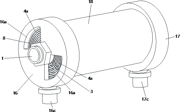
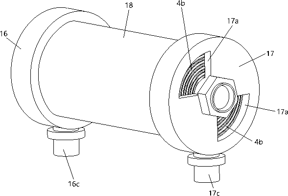
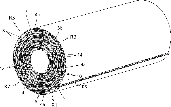
[0113]inFigure 8 withPicture 9 In this case, the area outside of the seventh radial direction R7 of each cold fluid outlet 5b is all blocked by the first baffle 6 to obtain a large enough hot fluid collection area. The area outside the sixth radial direction R6 of each hot fluid outlet 4b is all blocked by the second baffle 7 to obtain a sufficiently large cold fluid collection area. The area of ​​each cold fluid inlet 5a outside the second radial direction R2 is completely blocked by the sixth baffle 11 to obtain a sufficiently large hot fluid collection area. The area outside the first radial direction R1 of each hot fluid inlet 4a is all blocked by the seventh stopper 12 to obtain a sufficiently large cold fluid collection area.

[0114]inimage 3 withFigure 4 In the first embodiment shown, each of the above-mentioned barriers, namely the first barrier 6, the second barrier 7, the third barrier 8, the fourth barrier 9, the fifth barrier 10, and the sixth barrier The barrier bars 11, ...


PUM


Abstract

The invention relates to a spiral heat exchanger and a manufacturing method thereof. The spiral heat exchanger comprises a mandrel with the axis extending leftwards and rightwards and heat conductionthin strips spirally wound around the periphery of the mandrel by at least three circles. The heat conduction thin strips of any two adjacent ring layers are spaced by a certain distance, blocking ribs extending left and right are arranged between the heat conduction thin strips of any two adjacent ring layers in a supporting mode, all the blocking ribs are sequentially arranged in the radial direction of the mandrel, so that a plurality of hot fluid flow channel and a plurality of cold fluid flow channels alternately arranged in the radial direction of the mandrel are formed, each cold fluidoutlet is provided with a first barrier strip for partially blocking the cold fluid outlet, each hot fluid outlet is provided with a second barrier strip for partially blocking the hot fluid outlet, the first barrier strips are sequentially arranged in the first radial direction, and the second barrier strips are sequentially arranged in the second radial direction. The spiral heat exchanger is compact and ingenious in structure, small in flow resistance, large in heat exchange area, high in heat exchange efficiency and quite suitable for gas-gas heat exchange and gas-liquid heat exchange.

Description

Technical field[0001]This application relates to the field of heat exchange, in particular to a spiral heat exchanger and a manufacturing method thereof.Background technique[0002]Heat exchanger refers to the equipment that transfers the heat of the hot fluid to the cold fluid. Heat exchangers have important applications in daily life and industrial production. Due to the pursuit of larger heat exchange area, traditional heat exchangers generally occupy a larger area Therefore, it has disadvantages such as high requirements for installation space and inconvenient maintenance. Therefore, under the premise of ensuring sufficient heat exchange area, how to reduce the volume of the heat exchanger is an urgent problem in the industry.[0003]The Chinese utility model patent with publication number 204495135U discloses a new type of spiral plate reaction heat exchanger, which includes a first thin plate, a second thin plate, an intermediate partition and an outer cylinder, wherein the first ...

Claims


Application Information

Patent Timeline
Patent Type & Authority Applications(China)
IPC IPC(8): F28D9/04F28F9/22B21D53/04
CPCF28D9/04F28F9/22B21D53/04F28F2009/224
Inventor 高峰刘在祥陈艳凤蔡园丰王兵牛争艳
Owner SHANGHAI XINGYE MATERIALS TECH CO LTD
Why Eureka
Try Eureka