
A wind tunnel diaphragm clamping device

A clamping device and diaphragm technology, which is used in measuring devices, testing of machine/structural components, instruments, etc., can solve problems such as difficult on-site cleaning, poor clamping of diaphragms, and difficulty in replacing sealing rings, so as to improve reliability. and safety, reducing processing and manufacturing costs, and convenient use and maintenance.

Active Publication Date: 2022-04-22
中国空气动力研究与发展中心超高速空气动力研究所
View PDF10 Cites 0 Cited by
  • Summary
  • Abstract
  • Description
  • Claims
  • Application Information

AI Technical Summary

Problems solved by technology

[0004] The hydraulic clamping mechanism uses a part of the shock wave pipe section as the piston in the hydraulic cylinder, and realizes the clamping and loosening of the diaphragm by adjusting the pressure difference of the hydraulic oil at both ends of the piston. The advantage of the hydraulic clamping mechanism is that the device is simple and the diaphragm clamps The tightening force is large; the disadvantage is that the size of the large hydraulic clamping mechanism is large, and it is inconvenient to manufacture and use, which limits the application of the hydraulic clamping mechanism in large shock wave wind tunnels
[0005] It is technically feasible to insist on using a large-scale hydraulic clamping mechanism on large-scale high-enthalpy pulse equipment. However, due to the large size of the large-scale hydraulic clamping mechanism and the large sealing area, once the large-area seal is partially worn, it will cause The seal fails as a whole, and the seal failure will bring a series of difficult problems: first, the seal ring must be replaced after the seal failure occurs, and it is very difficult to replace the seal ring on a large hydraulic clamping mechanism
Secondly, the failure of the seal will also lead to oil leakage and environmental pollution, and it is very difficult to clean up the site
Thirdly, after the seal fails, because the pressure difference between the two ends of the piston in the hydraulic cylinder is not enough, the film clamping force is not enough, and the diaphragm is not clamped tightly, which will bring great safety hazards to the operation of equipment using hydrogen as the driving gas
Therefore, once the seal fails, it will take a long time to repair it, which will inevitably cause the large-scale high-enthalpy pulse equipment to fail to operate for a long time, and seriously reduce the test efficiency of the large-scale high-enthalpy pulse equipment
[0006] The full-thread clamping mechanism and the cut-off thread clamping mechanism have the advantages of compact structure, high connection strength and rigidity, but due to the use of thread connection, transmission and loading, the use and operation of large-scale thread clamping mechanisms are very inconvenient, and replacement If the diaphragm time is too long, it will also reduce the test efficiency of large high-enthalpy pulse equipment

Method used


Image

  • A wind tunnel diaphragm clamping device
  • A wind tunnel diaphragm clamping device
  • A wind tunnel diaphragm clamping device

Examples


Embodiment 1

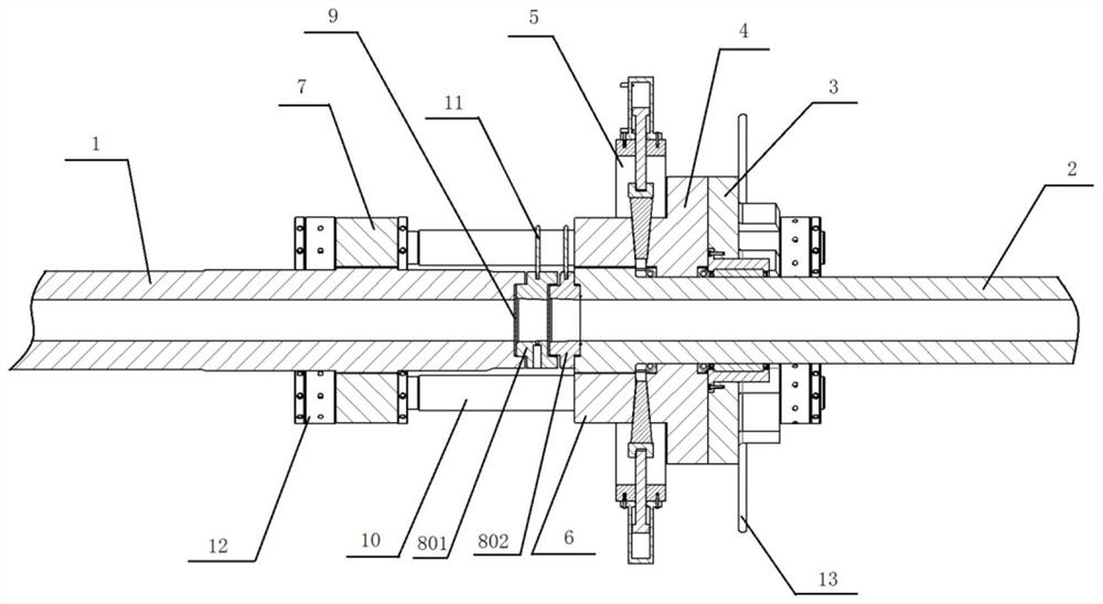
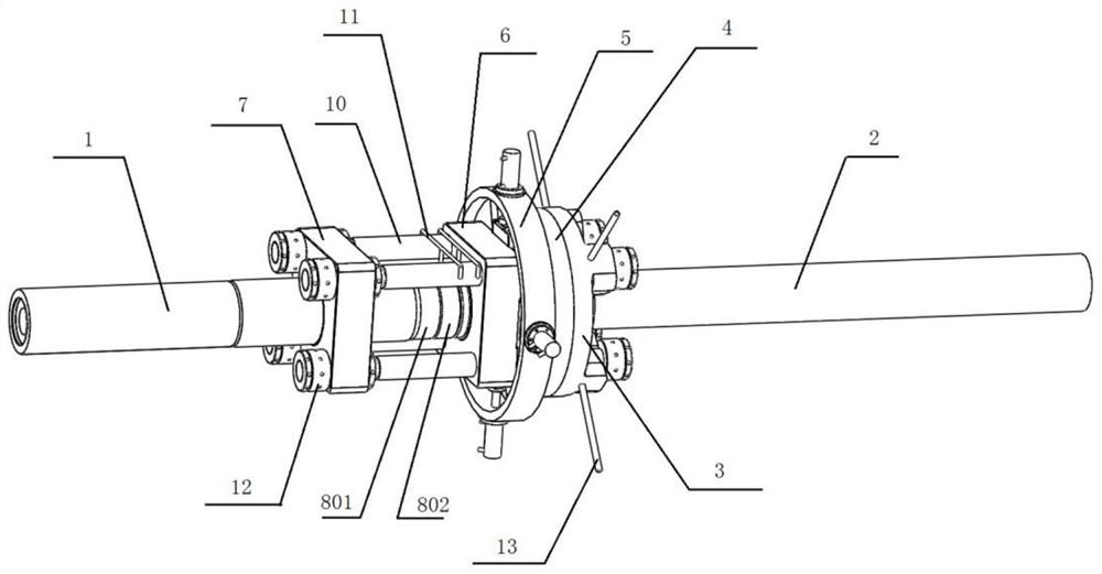
[0049] After a large-scale shock wave wind tunnel blowing test is completed, the broken diaphragm 9 needs to be replaced. At this time, the diaphragm clamping device of the wind tunnel is in the figure 2 Clamped state shown.

[0050] The specific replacement process is as follows:

[0051] 1. The wedge 15 is pulled out by the piston of the hydraulic cylinder 14, and the locked wedge 15 is released;

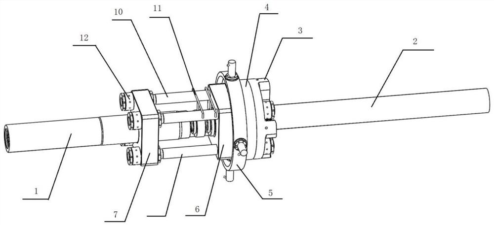
[0052] 2. Move the crowbar 13, turn the pressure block 3, so that the nut 12 on the pull rod 10 is rotated from the position of the boss 20 to such as image 3 The position of the groove 21 is shown;

[0053] 3. Use the traction system of the large-scale shock tunnel to pull the upstream pipe section 1 to the upstream direction, and then take out the broken diaphragm 9 and replace it with a new diaphragm 9;

[0054] 4. Use the wind tunnel diaphragm clamping device of the present invention to clamp the diaphragm 9 in reverse steps for the next test.


PUM


Abstract

The invention discloses a wind tunnel diaphragm clamping device. The clamping device includes an upstream pipe section, a sandwich ring and a downstream pipe section arranged in sequence, the upstream pipe section is a moving section, and the downstream pipe section is a fixed section; it also includes an upstream end fixed flange set on the upstream pipe section, which is sequentially set on the downstream pipe section The downstream end fixed flange, the hydraulic cylinder ring seat, the movable extrusion block and the pressing block; the tie rods evenly distributed along the circumferential direction pass through the upstream end fixed flange, the downstream end fixed flange, and the hydraulic cylinder ring seat 1. Movable extrusion block and briquetting block, the front end of the pull rod is fixed on the front end face of the upstream end fixed flange through a nut, and the rear end of the pull rod is fixed on the rear end face of the briquetting block through a nut. The clamping device has simple and reliable structure, convenient use and maintenance, safe and stable operation, and is suitable for popularization and application in the construction of large-scale high-enthalpy pulse equipment.

Description

technical field [0001] The invention belongs to the field of high-enthalpy pulse equipment, and in particular relates to a wind tunnel diaphragm clamping device. Background technique [0002] In high-enthalpy pulse equipment such as shock wave wind tunnels and expansion tube wind tunnels, diaphragms are used to separate different sections of the high-enthalpy pulse equipment. Clamped to meet test requirements. [0003] At present, commonly used clamping mechanisms include hydraulic clamping mechanisms, full-thread clamping mechanisms, and cut-off thread clamping mechanisms. [0004] The hydraulic clamping mechanism uses a part of the shock wave pipe section as the piston in the hydraulic cylinder, and realizes the clamping and loosening of the diaphragm by adjusting the pressure difference of the hydraulic oil at both ends of the piston. The advantage of the hydraulic clamping mechanism is that the device is simple and the diaphragm clamps The tightening force is large; th...

Claims


Application Information

Patent Timeline
Patent Type & Authority Patents(China)
IPC IPC(8): G01M9/02G01M9/04
CPCG01M9/02G01M9/04
Inventor 吕治国赵荣娟廖振洋钟涌龚红明
Owner 中国空气动力研究与发展中心超高速空气动力研究所
Learn More