Test fixture, resistance test device and method, and conductivity test method

A test fixture and resistance test technology, applied in the direction of measuring resistance/reactance/impedance, measuring device, measuring device casing, etc., can solve the problems of conductivity error, affecting the judgment of finished products, and the length of the wire cannot be determined, so as to ensure convenience performance, improve accuracy, and improve convenience

Pending Publication Date: 2021-01-05
NANTONG HUIFENG ELECTRONICS TECH
View PDF0 Cites 1 Cited by
  • Summary
  • Abstract
  • Description
  • Claims
  • Application Information

AI Technical Summary

Problems solved by technology

[0005] Therefore, the technical problem to be solved by the present invention is that during the conductivity testing process in the prior art, due to the large torsion resistance of the thicker copper-clad steel wire and a certain arc in the production process, during the straightening and clamping process, The length of the measured wire cannot be determined, which leads to errors in the measured conductivity and affects the judgment of the final product

Method used


Image

  • Test fixture, resistance test device and method, and conductivity test method
  • Test fixture, resistance test device and method, and conductivity test method
  • Test fixture, resistance test device and method, and conductivity test method

Examples


Embodiment 1

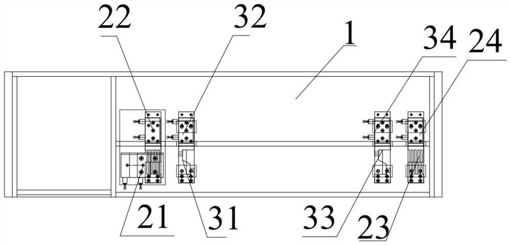
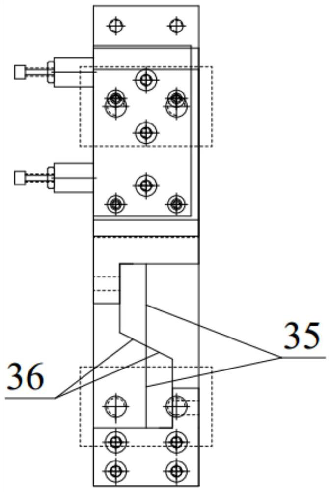
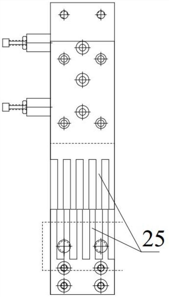
[0059] This embodiment provides a test fixture, such as Figure 1 to Figure 3 As shown, it includes: a substrate 1, a pre-clamping mechanism, a clamping mechanism and a driving mechanism. Wherein, both the pre-clamping mechanism and the clamping mechanism are installed on the base plate 1, and the driving mechanism drives the movement of the clamping mechanism and the pre-clamping mechanism. The pre-clamping mechanism includes two pre-clamping parts, and the pre-clamping parts form a pre-clamping space for clamping the test piece; the clamping mechanism includes a pair of measuring clamping parts, and any measuring clamping part has a The clamping space of the test piece; a pair of measuring clamps encloses the measurement space of the test piece, and the two pre-clamping pieces are placed on both sides of the measurement space.

[0060] In other optional embodiments, the pre-clamps can be set as two pairs, three pairs or more. Of course, it needs to be ensured that any pre-c...

Embodiment 2

[0077] This embodiment provides a resistance testing device, including: a measuring mechanism and the test fixture in Embodiment 1. Wherein, the measuring mechanism is used for testing the resistance of the test piece arranged in the measurement space along the extending direction of the length of the test piece.

[0078] Specifically, the object to be tested in this embodiment is a copper-clad steel wire as an example, and the measuring mechanism includes a micro-ohmmeter for measuring resistance.

Embodiment 3

[0080] This embodiment provides a resistance testing method, comprising the following steps:

[0081] S1: Installation: at least two pre-clamps are installed on the outside of the measurement space formed by the two measuring clamps;

[0082] S11: Install the first measuring fixture and the second measuring fixture on the substrate 1

[0083] S12: Install the first pre-clamp on the left side of the first measurement clamp, install the second pre-clamp on the right side of the second measurement clamp, and ensure that the first pre-clamp teeth 21 and the third pre-clamp The points where the tooth tips of the tooth 23 , the first measuring tooth 31 , and the third measuring tooth 33 are located or the surfaces where the tooth tips are located are coplanarly arranged.

[0084] S2: Pre-clamping: the pre-clamping part clamps the part to be tested;

[0085]S21: Place the test piece on the first pre-clamping tooth 21 and the second pre-clamping tooth 22, the first measuring tooth 3...


PUM


Abstract

The invention discloses a test fixture, a resistance test device and method, and a conductivity test method. The test fixture comprises a substrate, a pre-clamping mechanism and a clamping mechanism,wherein the pre-clamping mechanism and the clamping mechanism are installed on the substrate. The pre-clamping mechanism comprises at least two pre-clamping pieces, and any pre-clamping piece forms apre-clamping space used for clamping a to-be-tested piece; the clamping mechanism comprises measuring clamping pieces arranged in pairs, and any measuring clamping piece is provided with a clamping space used for clamping the to-be-tested piece. A measuring space is defined by the pair of measuring clamping pieces; the clamping mechanism is provided with at least two pre-clamping pieces arranged on the two sides of the measuring space respectively, and when the pre-clamping pieces clamp the to-be-tested piece, the measuring clamping pieces clamp the measurement state of the to-be-tested piece.The accuracy of length measurement to be measured in the clamping process is improved, the accuracy of conductivity measurement is further improved, and the influence on final finished product judgment is avoided.

Description

technical field [0001] The invention relates to the technical field of testing, in particular to a testing fixture, a resistance testing device and method, and a conductivity testing method. Background technique [0002] Conductivity, also known as electrical conductivity, is a measure of the ability of a substance to transmit electric current. When a voltage is applied across the conductor, its charge carriers will flow in a certain direction, thus generating a current. [0003] The conductivity of the wire is one of the important test parameters to test whether the production wire meets the requirements of the finished product, and the measurement of the conductivity is usually used. Usually, the resistance of a certain length of wire is measured by a measuring device, and the resistance of the wire is obtained by measuring the thickness of the wire rate, and finally calculate the conductivity through the resistivity, and compare it with the preset standard to finally get...

Claims


Application Information

Patent Timeline
Patent Type & Authority Applications(China)
IPC IPC(8): G01R27/02G01R1/04
CPCG01R1/0425G01R27/02
Inventor 石明华宋小波陈健蔡成俊
Owner NANTONG HUIFENG ELECTRONICS TECH
Why Eureka
Try Eureka