
MT insertion core structure

A ferrule and channel technology, which is applied in light guides, optics, instruments, etc., can solve problems such as uneven adhesive layer thickness, weakened strength, and easy breakage, so as to improve product reliability, increase module internal space, and enhance optical fiber protection. Effect

Pending Publication Date: 2021-01-05
OECE COMM
View PDF0 Cites 2 Cited by
  • Summary
  • Abstract
  • Description
  • Claims
  • Application Information

AI Technical Summary

Problems solved by technology

[0003] However, this conventional structure has several defects: 1. The existence of the dispensing window makes the thickness of the optical fiber, especially the adhesive layer around the junction point of the optical fiber cladding and the optical fiber coating layer, uneven, which has a negative impact on reliability; 2. .The existence of the dispensing window causes the ferrule to have weak lateral strength, making it easy to damage during production and use; 3. The length of the fiber guide groove is not enough, and it is difficult to insert the fiber into the fiber, so a microscope is needed; 4. The end is reserved Through the hollow space of the tail pipe, the edge wall thickness of the guide holes at both ends is not enough, the strength becomes weak, and it is easy to break

Method used


Image

  • MT insertion core structure
  • MT insertion core structure
  • MT insertion core structure

Examples


Embodiment Construction

[0030] The present invention will be further described below in conjunction with accompanying drawing, and the structure and principle of the present invention are very clear to those skilled in the art. It should be understood that the specific embodiments described here are only used to explain the present invention, not to limit the present invention.

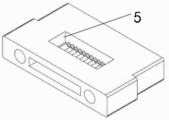
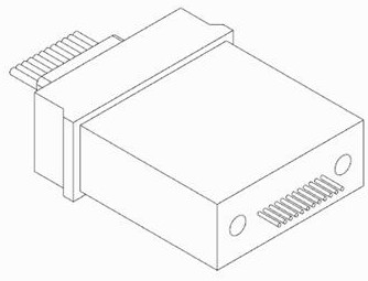
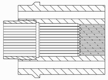
[0031] Figure 5-7 Shown is the MT ferrule structure designed by the present invention, including the ferrule body, the front end of the ferrule body is provided with a fiber cladding channel 1, the rear end of the ferrule body is provided with a fiber coating channel 2, and the fiber cladding channel 1 is used to fix the fiber cladding, the fiber coating channel 2 is used to fix the fiber coating, the transition between the fiber cladding channel 1 and the fiber coating channel 2 is guided, the ferrule body has two There are front and rear guide holes 3 at the end, the top and bottom of the ferrule body are closed, and the...


PUM


Abstract

The invention relates to the technical field of optical fiber connector components, in particular to an MT insertion core structure, which comprises an insertion core body, an optical fiber cladding channel is formed in the front section of the interior of the insertion core body and used for positioning and fixing an optical fiber cladding, and front-back guide holes are formed in the left end and the right end of the insertion core body. The MT insertion core structure is characterized in that: an optical fiber coating layer channel is formed in the rear section in the insertion core body and used for fixing an optical fiber coating layer, guide transition is formed between the optical fiber cladding layer channel and the optical fiber coating layer channel, the top and the bottom of theinsertion core body are closed, a dispensing opening is formed in the tail end in the insertion core body , and a dispensing window is removed from the insertion core body, the top and the bottom areclosed, so that the strength is higher; the optical fiber cladding channel and the optical fiber coating layer channel are arranged in the insertion core body, the optical fiber cladding channel fixes the optical fiber cladding, the optical fiber coating layer channel fixes the optical fiber coating layer, optical fibers can be well protected, guide transition exists between the channels, opticalfiber protection is enhanced, and product reliability is improved.

Description

technical field [0001] The invention relates to the technical field of optical fiber connector components, in particular to an MT ferrule structure. Background technique [0002] MT ferrule is a connection part used for optical fiber connectors, usually used as the connector of optical fiber connectors, with channels inside for fixing optical fibers, and guide holes or guide posts on both sides as docking references. Such as Chinese patent: a MT ferrule, patent number: 2017200797198. The usual structure of the MT ferrule shown in 2017200797198 is that the inner front end is provided with a fiber guide groove for fixing the fiber cladding, and the inner rear end is provided with a hollow part for It is connected with the tail pipe, with a dispensing window on the top for dispensing and fixing the fixed optical fiber. [0003] However, this conventional structure has several defects: 1. The existence of the dispensing window makes the thickness of the optical fiber, especiall...

Claims


Application Information

Patent Timeline
Patent Type & Authority Applications(China)
IPC IPC(8): G02B6/38
CPCG02B6/3847G02B6/3855G02B6/3869
Inventor 金建峰刘光兵
Owner OECE COMM
Learn More