
Gate driving unit, gate driving method, gate driving circuit and display device

A gate drive and control circuit technology, applied in the fields of gate drive, gate drive circuit and display device, gate drive unit, can solve the problems of unfavorable narrow frame, large number of transistors, etc.

Pending Publication Date: 2021-01-05
BOE TECH GRP CO LTD +1
View PDF0 Cites 6 Cited by
  • Summary
  • Abstract
  • Description
  • Claims
  • Application Information

AI Technical Summary

Problems solved by technology

[0003] The main purpose of the present invention is to provide a gate drive unit, a gate drive method, a gate drive circuit and a display device, which solve the problem of providing an N-type transistor in an LTPO (low temperature polycrystalline oxide) pixel circuit in the prior art. When using a polar drive signal, the number of transistors used is large, which is not conducive to the realization of narrow borders

Method used


Image

  • Gate driving unit, gate driving method, gate driving circuit and display device
  • Gate driving unit, gate driving method, gate driving circuit and display device
  • Gate driving unit, gate driving method, gate driving circuit and display device

Examples


Embodiment Construction

[0060] The following will clearly and completely describe the technical solutions in the embodiments of the present invention with reference to the accompanying drawings in the embodiments of the present invention. Obviously, the described embodiments are only some, not all, embodiments of the present invention. Based on the embodiments of the present invention, all other embodiments obtained by persons of ordinary skill in the art without making creative efforts belong to the protection scope of the present invention.

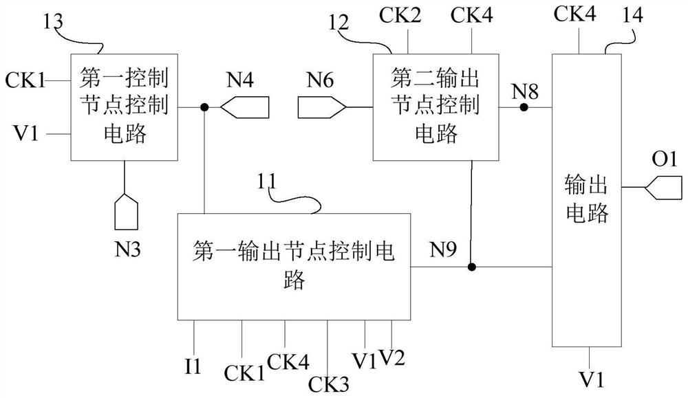
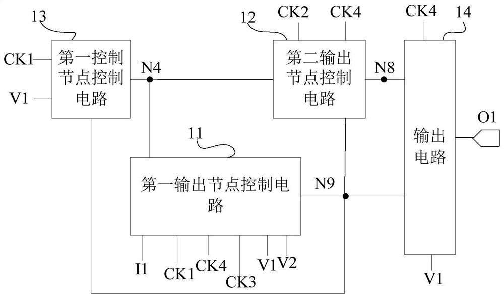
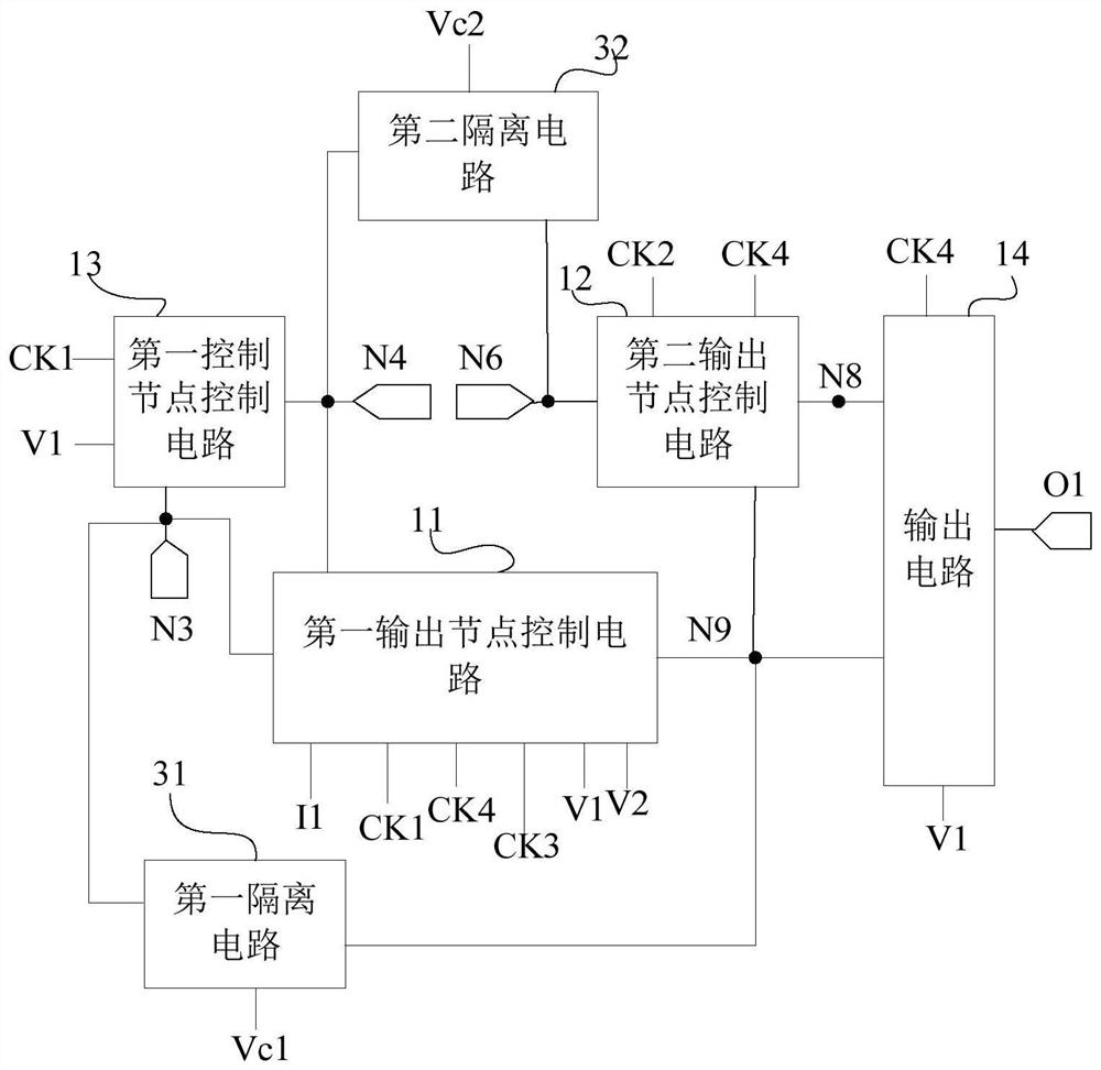
[0061] Such as figure 1 As shown, the gate drive unit according to the embodiment of the present invention includes a first clock signal terminal, a second clock signal terminal, a third clock signal terminal, a fourth clock signal terminal, a first output node control circuit 11, a second output node Node control circuit 12, first control node control circuit 13 and output circuit 14, wherein,

[0062] The first output node control circuit 11 is respectively...


PUM


Abstract

The invention provides a gate driving unit, a gate driving method, a gate driving circuit and a display device. The gate driving unit comprises a first clock signal end, a second clock signal end, a third clock signal end, a fourth clock signal end, a first output node control circuit, a second output node control circuit, a first control node control circuit and an output circuit. According to the invention, the gate driving signal required by the N-type transistor can be provided for the LTPO (Low Temperature Polycrystalline Oxide) pixel circuit, the number of adopted transistors can be reduced, and a narrow frame can be realized.

Description

technical field [0001] The present invention relates to the field of display technology, in particular to a gate drive unit, a gate drive method, a gate drive circuit and a display device. Background technique [0002] In related gate drive units applied to LTPO (low temperature polycrystalline oxide) pixel circuits, generally the P-type transistor outputs the gate drive signal required by the P-type transistor, and then the N-type transistor is obtained through the inverter. For the required gate driving signal, the number of transistors required to be used in the related gate driving unit applied to the LTPO pixel circuit is large. Contents of the invention [0003] The main purpose of the present invention is to provide a gate drive unit, a gate drive method, a gate drive circuit and a display device, which solve the problem of providing an N-type transistor in an LTPO (low temperature polycrystalline oxide) pixel circuit in the prior art. When the polar drive signal i...

Claims


Application Information

Patent Timeline
Patent Type & Authority Applications(China)
IPC IPC(8): G09G3/20
CPCG09G3/20G09G2310/0286G09G3/3674G09G3/3266G11C19/28G09G3/2092G09G2300/0852G09G2310/0267
Inventor 李文强姜春桐石领陈义鹏谢帅
Owner BOE TECH GRP CO LTD
Learn More