Winding direction alternate continuous coil winding device and method

A winding device and winding direction technology, which is applied in coil manufacturing, electromechanical devices, and motor generator manufacturing, can solve the problems of difficult control of wire length, low winding efficiency, and manual counting, so as to improve reliability and practicality. performance, improved winding efficiency, and easy operation

Active Publication Date: 2022-06-21
CSR ZHUZHOU ELECTRIC CO LTD
View PDF11 Cites 0 Cited by
  • Summary
  • Abstract
  • Description
  • Claims
  • Application Information

AI Technical Summary

Problems solved by technology

[0004] 1. Two people circle around the winding mold, and the winding efficiency is low;
[0005] 2. The operator always turns around the vertical winding die during the coil winding process, which is easy to fatigue;
[0006] 3. The number of turns of the coil needs to be manually counted (the number of turns per person), which is easy to make mistakes;
[0007] 4. The length of the connection between the two double pie coils is difficult to control
[0014] On the basis of realizing the power winding of the equipment, how to alternately change the winding direction of the wound double cake coil to form a continuous winding direction alternating coil is not disclosed in the existing patent documents

Method used


Image

  • Winding direction alternate continuous coil winding device and method
  • Winding direction alternate continuous coil winding device and method
  • Winding direction alternate continuous coil winding device and method

Examples


Embodiment Construction

[0046] Combine below Figure 1 to Figure 8 The embodiments of the present invention will be described in detail.

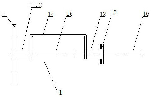
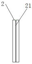
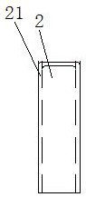
[0047] The winding direction alternating continuous coil winding device is characterized in that: it includes a winding device 1 for winding continuous double-cake coils and changing the winding direction of the double-cake coils alternately; The wire is bent into a U-shaped connecting wire bending plate 2. The winding device 1 is detachably connected to the faceplate of the winding machine, and the coil is wound with the rotation of the faceplate of the winding machine, and the winding direction is alternately changed, and the phase is changed. The connecting lines between adjacent double-cake coils are bent into a U-shape with a connecting wire bending plate 2 to form a continuous coil in which left-wound double-cake coils and right-wound double-cake coils alternate.

[0048]In the above-mentioned alternate winding continuous coil winding device, the winding de...


PUM


Abstract

Winding direction alternating continuous coil winding device, including a winding device that winds continuous double-cake coils and alternately changes the winding direction of double-cake coils, and is used to bend the connecting line between adjacent double-cake coils into a U type connecting bending plate, the winding device is detachably connected with the faceplate of the winding machine, and the coil is wound with the rotation of the faceplate of the winding machine and the winding direction is alternately changed, and the adjacent double-cake coils The connecting wire is bent into a U shape with a connecting wire bending plate to form a continuous coil in which a left-winding double-cake coil and a right-winding double-cake coil alternate. The invention realizes the power winding of the equipment, reduces labor intensity, improves production efficiency, ensures that the number of turns of the coil meets the requirements of the drawing, and ensures product quality. The baffles are installed on different ends of the winding mold to form reverse winding. Alternate change of direction is achieved by alternately installing baffles to both ends of the winding die, which is easy to operate and improves winding efficiency. The invention also relates to a coil winding method of alternating direction and continuous type.

Description

technical field [0001] The present invention relates to a device and a method for winding a continuous coil with alternate winding directions, which are used for the winding of a continuous coil. Background technique [0002] An oil field linear motor coil is a continuous coil, and its winding directions are alternately left and right, that is, the first two cakes are left wound, and the last two cakes are right wound, and so on and so forth. The existing winding method is that two people hold the calculated length of wire (one person holds the wire required for a cake coil, and the other person holds the wire required for the entire coil), and turns around the vertical winding die (one person holds the wire required for the entire coil). Rotate the circle clockwise, one person rotates the circle counterclockwise), the two people rotate the coil around the vertical winding die at the same time for the required number of circles. One person holds the pie while holding the wi...

Claims


Application Information

Patent Timeline
Patent Type & Authority Patents(China)
IPC IPC(8): H01F41/082H01F41/098H01F41/06H02K15/04
CPCH01F41/082H01F41/098H01F41/06H02K15/0435
Inventor 陈建平施超贺健凌浩谭杨唐澎
Owner CSR ZHUZHOU ELECTRIC CO LTD
Why Eureka
Try Eureka