Eureka AIR delivers breakthrough ideas for toughest innovation challenges, trusted by R&D personnel around the world.

Thyristor parallel connection alternate conduction rectifying circuit silicon controlled rectifier/thyristor

A rectifier circuit, alternating conduction technology, applied in the direction of converting AC power input to DC power output, irreversible AC power input converting to DC power output, electrical components, etc., can solve the problem of uncontrolled current size and shortened switching power supply life. , the reliability of the device cannot be guaranteed, etc.

Inactive Publication Date: 2021-01-05
SHANGHAI JUNTAO POWER EQUIP CO LTD
View PDF7 Cites 2 Cited by
  • Summary
  • Abstract
  • Description
  • Claims
  • Application Information

AI Technical Summary

Problems solved by technology

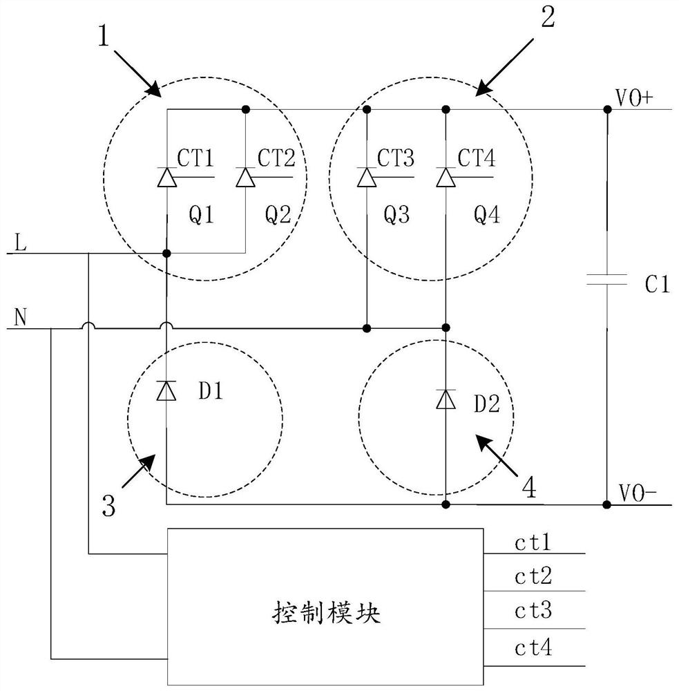
[0003] In the existing half-controlled bridge rectifier circuit using thyristors and diodes, when the load power is large and the input current is large, any bridge arm composed of thyristors needs to be connected in parallel with two thyristors to bear the current stress. The thyristors used in parallel When the control signal is the same control signal, it is turned on and off at the same time, and the input current flows into the two thyristors at the same time, but the magnitude of the current flowing through them is not controlled and is determined by the difference of their respective parameters. The current cannot be evenly distributed, and it is easy to cause more heat to be generated by devices with larger currents, the reliability of the devices cannot be guaranteed, and the life of the entire switching power supply will be greatly reduced

Method used


Image

  • Thyristor parallel connection alternate conduction rectifying circuit silicon controlled rectifier/thyristor
  • Thyristor parallel connection alternate conduction rectifying circuit silicon controlled rectifier/thyristor

Examples


Embodiment Construction

[0021] The following will clearly and completely describe the technical solutions in the embodiments of the present invention with reference to the accompanying drawings in the embodiments of the present invention. Obviously, the described embodiments are only some, not all, embodiments of the present invention. Based on the embodiments of the present invention, all other embodiments obtained by persons of ordinary skill in the art without creative efforts fall within the protection scope of the present invention.

[0022] It should be understood that the step numbers used herein are only for convenience of description, and are not intended to limit the execution order of the steps.

[0023] It should be understood that the terminology used in the description of the present invention is for the purpose of describing particular embodiments only and is not intended to limit the present invention. As used in this specification and the appended claims, the singular forms "a", "an"...


PUM


Abstract

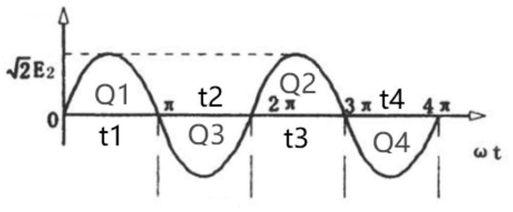
The invention provides a thyristor parallel connection alternate conduction rectifying circuit. The thyristor parallel connection alternate conduction rectifying circuit comprises a rectifying circuitand a control module, the control module is connected with the rectifying circuit through a control end and is used for controlling alternate conduction of thyristors connected in parallel in the rectifying circuit; a first bridge arm and a second bridge arm of an upper half bridge of the rectifying circuit are respectively composed of two thyristors which are connected in parallel. A third bridge arm and a fourth bridge arm of the lower half bridge are respectively composed of at least one diode; cathodes of the two thyristors connected in parallel on the first bridge arm and the second bridge arm are positive output ends of the rectifying circuit. The anodes of the diodes on the third bridge arm and the fourth bridge arm are the negative output ends of the rectifying circuit; the positive output end and the negative output end of the rectifying circuit are connected with the two ends of the capacitor respectively. The invention realizes the current sharing function of the two thyristors by controlling the thyristors used in parallel to conduct alternately.

Description

technical field [0001] The invention relates to the technical field of switching power supply applications, in particular to a thyristor parallel alternate conduction rectification circuit. Background technique [0002] Switching power supplies are essential and critical components in modern electronic systems. The function of the switching power supply is to convert the input voltage into an output voltage that meets the load requirements, and the rectifier circuit is the main part of the switching power supply. The function of the rectifier circuit is to convert the alternating current into a unidirectional pulsating direct current. [0003] In the existing half-controlled bridge rectifier circuit using thyristors and diodes, when the load power is large and the input current is large, any bridge arm composed of thyristors needs to be connected in parallel with two thyristors to bear the current stress. The thyristors used in parallel When the control signal is the same c...

Claims


Application Information

Patent Timeline
IPC IPC(8): H02M7/162H02M7/17
CPCH02M7/1626H02M7/17
Inventor 权良玉李华铭张余进厉干年
Owner SHANGHAI JUNTAO POWER EQUIP CO LTD
Why Eureka
Eureka Blog
Learn More