Desalting device

a technology of desalting device and sluice pipe, which is applied in the direction of water/sewage treatment by ion exchange, separation process, filtration separation, etc. it can solve the problems of ineffective use of space within the bulge portion, and achieve the effect of preventing unfavorable flow and reducing the flow rate of water passing through each strainer in the outer peripheral portion

Inactive Publication Date: 2016-04-26
KURITA WATER INDUSTRIES LTD
View PDF15 Cites 0 Cited by
  • Summary
  • Abstract
  • Description
  • Claims
  • Application Information

AI Technical Summary

Benefits of technology

[0011]It is an object of the present invention to provide a desalting device which includes a tower body having a bulge portion bulging downward from its bottom, and which prevents uneven flow and has no dead space within the tower body.
[0016]In the desalting device according to the second aspect, the flow rate of water passing through each strainer arranged in the outer peripheral portion is decreased, and it is preferable that the flow rate of water passing through the strainer at the central portion is equivalent to the major portion of total flow rate and that the flow rate of water passing through the strainer decreases as the strainer is located closer to the outer peripheral side. Thus, uneven flow is prevented. In addition, no dead space occurs also in the second aspect. An orifice is preferably provided in a water introducing pipe connected to each strainer whereby the flow rate of water passing through each strainer in the outer peripheral portion is decreased.

Problems solved by technology

In such a desalting device in which strainers are arranged at the same height, a space below the strainers 3 is a dead space, and the space within the bulge portion is not used effectively.

Method used


Image

  • Desalting device
  • Desalting device
  • Desalting device

Examples


example 1

[0046]The desalting device in which the strainers are arranged in the central region will be described in more detail by means of examples.

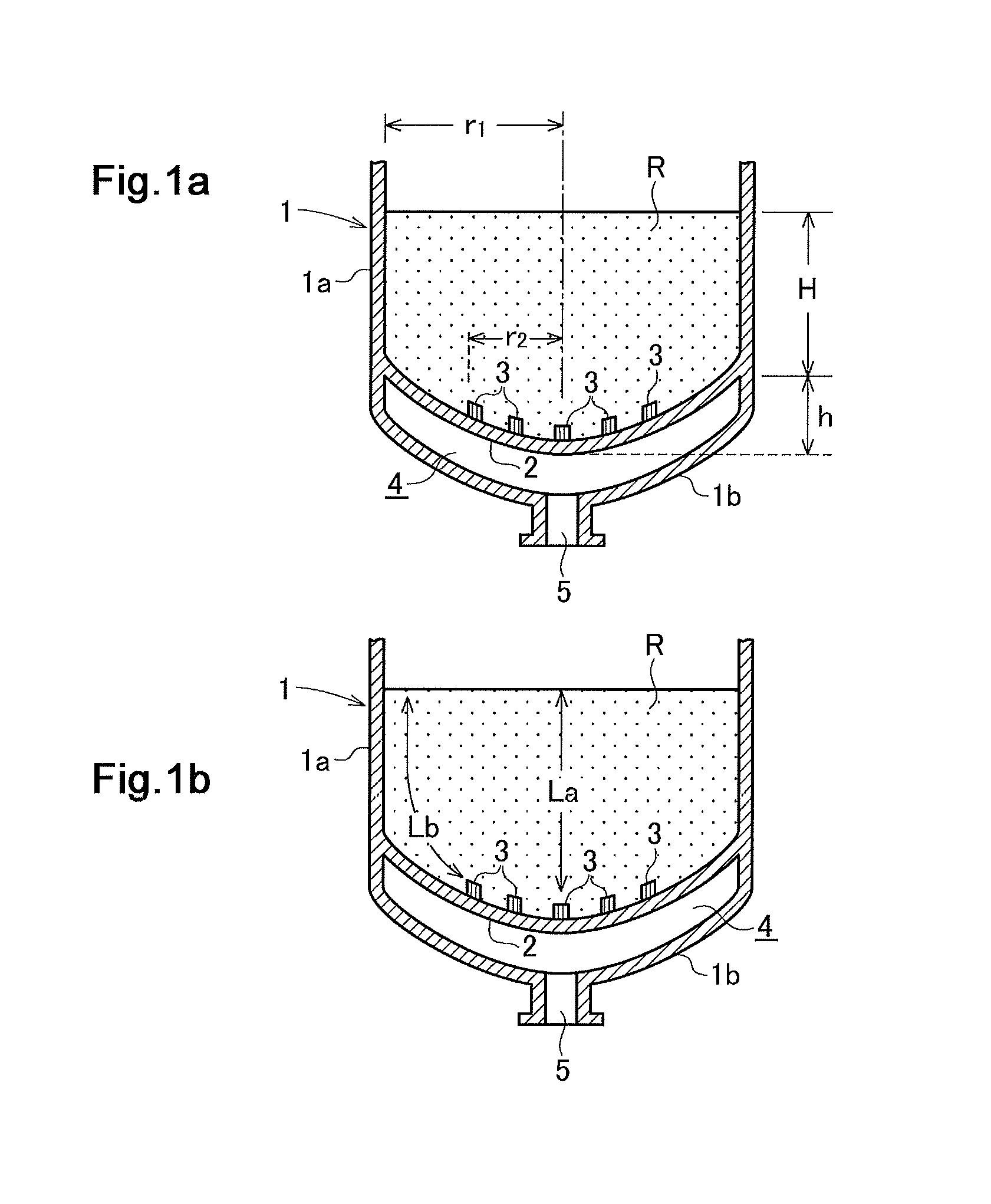
[0047]In Example 1, the effects were verified using CFD (computational fluid dynamics) software. The setting conditions are as follows.[0048]Diameter of tower body: 3706 mm[0049]H: 871.5 mm[0050]h: 315.5 mm[0051]H+h: 1187 mm[0052]Radius of curvature of bulge portion: 5600 mm[0053]Radius of curvature of joint portion between bulge portion and straight body portion: 222 mm[0054]Flow rate of passing water: 0.35 m3 / sec

[0055]In Example 1, the arrangement of the water collecting strainers is divided into 8 radial positions of 10 to 100% from the central portion. In analysis, a tracer substance was put uniformly over the entirety of the surface of the resin bed at analysis time 0 [sec.], and injected in only the interval of analysis times 0 to 1 [sec.]. An analysis time step was advanced until the total amount of the tracer substance passed into the wat...

example 2

[0062]An example of a desalting device in which the collected water volume of each strainer was made equal to each other by orifices will be described.

[0063]In Example 2, the effects were verified using CFD (computation fluid dynamics) software. The setting conditions are as follows:[0064]Diameter of tower body: 3520 mm[0065]H: 600 mm[0066]h: 679 mm[0067]H+h: 1279 mm[0068]Radius of curvature of bulge portion: 3520 mm[0069]Radius of curvature of joint portion between bulge portion and straight body portion: 352 mm[0070]Flow rate of passing water: 0.35 m3 / sec

[0071]In Example 2, the case where no orifice nozzle was provided was defined as a case a, and the case where orifice nozzles were provided was defined as a case b.

[0072]In the cases a and b, the water collecting strainers were classified into seven sections (A to G sections) on the basis of the distance from the ion-exchange resin surface to the nozzle lower end (i.e., into seven sections on the basis of the distance from the cen...


PUM

PropertyMeasurementUnit
analysis timeaaaaaaaaaa
areaaaaaaaaaaa
flow rateaaaaaaaaaa

Abstract

Provided is a desalting device which includes a tower body and a bulge portion bulging downward therefrom, and which prevents uneven flow and causes no dead space within the tower body. The desalting device includes a tower body having a bulge portion 1b bulging downward at a bottom portion thereof, an ion-exchange resin packed in the tower body, and a plurality of strainers 3 for collecting water being arranged within the bulge portion 1b. The strainers are arranged only in a central region of an inside of the bulge portion excluding an outer peripheral portion of the bulge portion.

Description

FIELD OF INVENTION[0001]The present invention relates to a desalting device including a tower body and an ion-exchange resin packed in the tower body, and particularly relates to a desalting device in which the tower body has a bulge portion bulging downward from the bottom thereof and a plurality of strainers for collecting water are arranged within the bulge portion.BACKGROUND OF INVENTION[0002]Desalting devices including a tower body and an ion-exchange resin packed therein have been widely used. The tower body has a bulge portion bulging downward from the bottom thereof, and a plurality of strainers are arranged on an inside of the bulge portion. The tower body having the bulge portion at its bottom portion has a high pressure resistance. FIG. 4 and FIGS. 5 and 6 show conventional desalting devices described in FIGS. 7 to 9 of Patent Literature 1.[0003]The desalting device shown in FIG. 4 includes a tower body 1 having a cylindrical straight body portion 1a and a bulge portion 1...

Claims


Application Information

Patent Timeline
Patent Type & Authority Patents(United States)
IPC IPC(8): C02F1/42B01J47/02
CPCC02F1/42B01J47/022
Inventor TERASHIMA, MITSUHARUIWASAKI, MAMORUIINO, HIDEAKI
Owner KURITA WATER INDUSTRIES LTD
Why Eureka
Try Eureka