Auxiliary paper feeding device of scanner

A scanner and paper feeding technology, applied in image communication, electrical components, etc., can solve the problems of affecting the scanning progress, the whole stack of paper collapses and leaves the paper feeding platform, and the whole stack of paper easily collapses and leaves the paper feeding platform, etc., to prevent collapse. Effect

Pending Publication Date: 2021-01-05
宁波华高信息科技有限公司
0 Cites 0 Cited by

AI-Extracted Technical Summary

Problems solved by technology

However, if some soft papers are placed on the feeding platform, such as test papers, etc., then during the scanning process, the entire stack of papers will easily collapse and fall off the feeding platform, which will affect the scanning ...

Method used

Concrete: in order to avoid that the paper pressing sheet 3 that packs up hinders the paper feeding of the paper to be scanned that is placed on the paper feed platform 1, the side wall of the paper feeding baffle plate 2 corresponding to the paper pressing sheet 3 has a slot, The bottom side of the paper pressing sheet 3 is integrally formed with a hollow connecting column, and both ends of the connecting column are provided with hinged joints, and a hinged column is integrally formed at the corresponding hinge joint of the embedded groove, and the paper pressing sheet 3 is hinged through the connecting column. The opening and the hinge column can be folded and hinged in the slot. By hinged the paper presser 3 in the slot, the user can hide the presser 3 in the paper feed baffle 2 when the user does not need to use the paper presser 3. Ensure the beauty of the paper storage bin.
In the present embodiment, in order to reduce the frictional force between bottom layer paper and paper feed platform 1, the first paper feed pallet 4 and the second paper feed pallet 5, convenient paper enters scanner smoothly and scans, Some modifications have also been made to the paper feeding platform 1 , the first paper feeding pallet 4 and the second paper feeding pallet 5 . Wherein, the paper feeding platform 1 is provided with at least one reinforcing rib 11 along the paper feeding direction, and a plurality of feeding pulleys 12 are arranged inside the reinforcing rib 11 . The paper is placed on the paper feeding platform 1, and the middle part of the paper is usually in close contact with the paper feeding platform due to gravity, and the middle part of the paper is lifted by setting the reinforcing rib 11, which is convenient for paper feeding and ensures that the paper feeding process is smooth. Card. The first paper feeding pallet 4 is also provided with a plurality of first reinforcing ribs along the paper feeding direction on the side that is in contact with the paper. Lift it up to facilitate paper feeding and ensure that the paper feeding process does not get stuck. The second paper feeding pallet 5 is also provided with a plurality of second reinforcing ribs along the paper feeding direction on the side abutting against the paper, and its function is the same as that of the first reinforcing ...

Abstract

The present invention discloses an auxiliary paper feeding device of a scanner. The device comprises a paper feeding platform, paper feeding baffles are arranged on the left side and the right side ofthe paper feeding platform respectively, a paper pressing piece is arranged on each paper feeding baffle, a first paper feeding supporting plate is arranged on the paper feeding platform in the paperfeeding direction, and the first paper feeding supporting plates are arranged in the paper feeding platform in an inwards-contracting mode. The paper pressing pieces are arranged on the paper feedingbaffles on the left side and the right side, the whole stack of paper can be prevented from collapsing, and a limiting effect is achieved; and through the first paper feeding supporting plate, the length of the paper feeding platform is increased, long paper can be better borne, and the whole stack of paper is prevented from collapsing.

Application Domain

Technology Topic

Image

  • Auxiliary paper feeding device of scanner
  • Auxiliary paper feeding device of scanner
  • Auxiliary paper feeding device of scanner

Examples

  • Experimental program(1)

Example Embodiment

[0020]The embodiments of the present invention will be further described below in conjunction with the drawings.
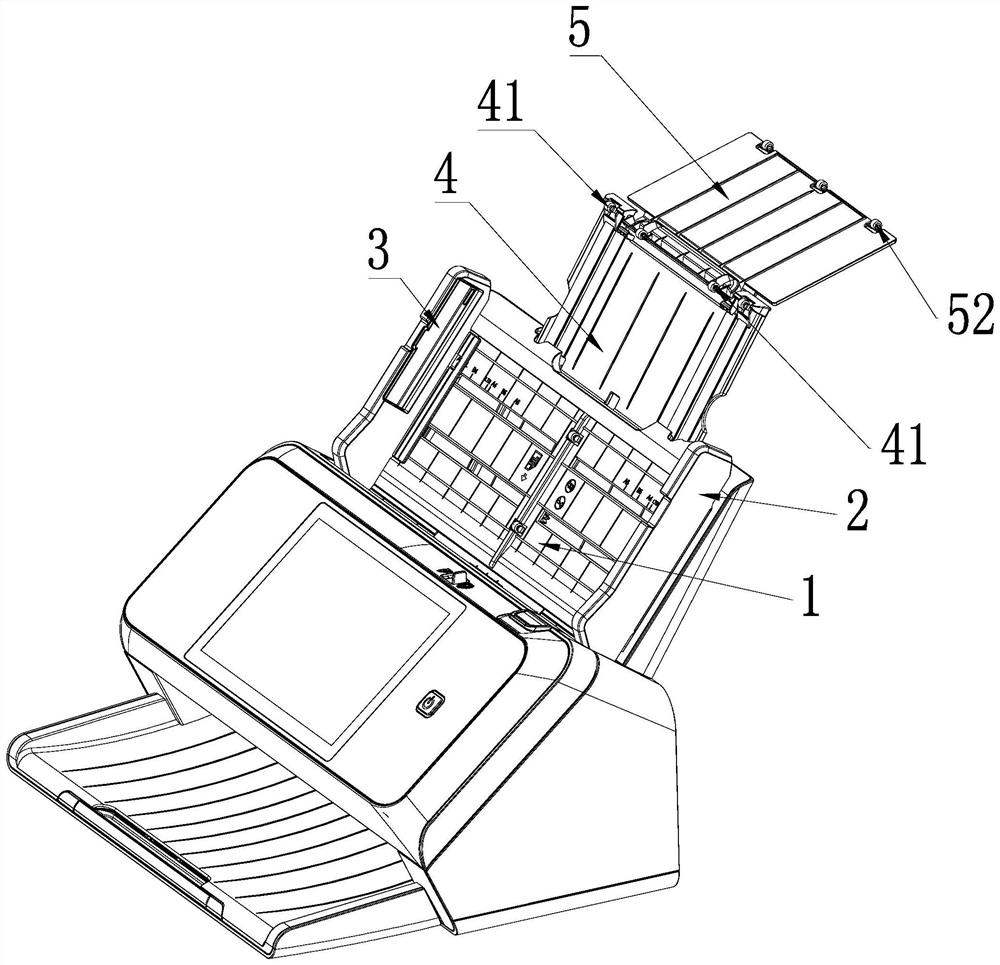
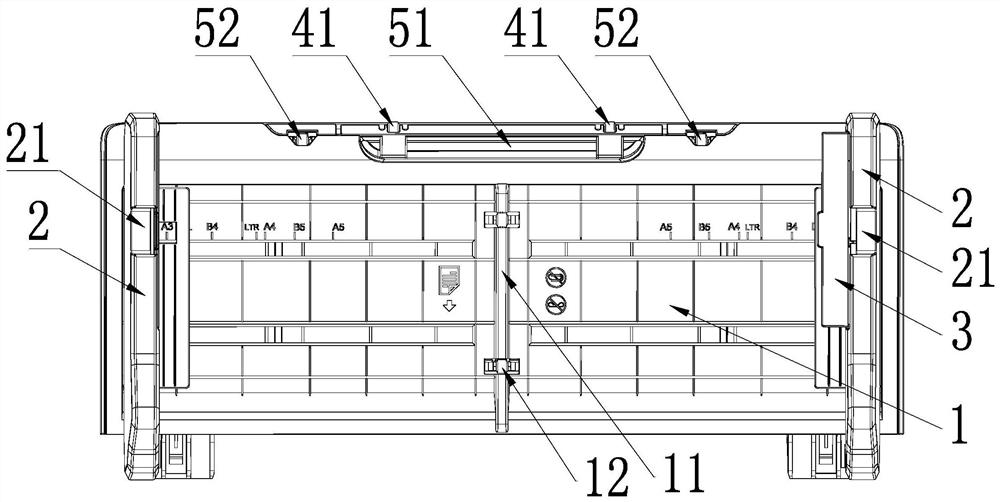
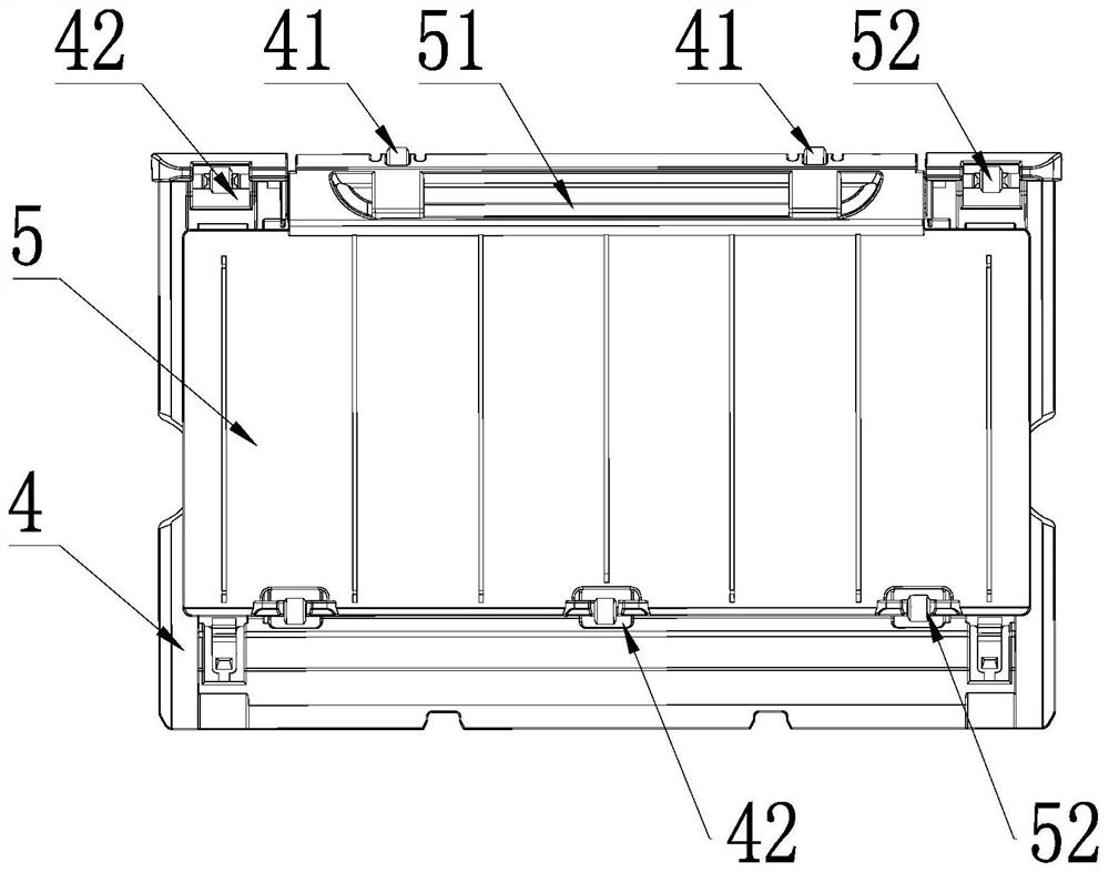
[0021]Such asFigure 1-5As shown, this embodiment relates to an auxiliary paper feeding device of a scanner, which includes a paper feeding platform 1, and paper feeding baffles 2 are provided on the left and right sides of the paper feeding platform 1.
[0022]In this embodiment, a paper pressing sheet 3 is provided on the paper feed baffle 2. The paper pressing sheet 3 and the paper feed baffle 2 are used to perform a preliminary limit pressing on both ends of the paper to prevent the entire stack of soft paper from collapsing during the scanning and feeding process.
[0023]The paper pressing sheet 3 is embedded in the inner side wall of the paper feed baffle 2 and is hinged to the inner side wall of the paper feed baffle 2. Through this design, when scanning ordinary paper, the paper pressing plate 3 can be received into the paper feeding baffle 2; when the soft paper needs to be restricted, the paper pressing plate 3 can be opened, which is convenient for operation.
[0024]Specifically: In order to prevent the stowed paper plate 3 from obstructing the feeding of the paper to be scanned placed on the paper feeding platform 1, the paper feed baffle 2 is provided with an inset groove on the side wall corresponding to the paper plate 3, and the paper plate The bottom side of 3 is integrally formed with a hollow connecting column, and both ends of the connecting column are provided with hinge joints, and the hinge joint is integrally formed with a hinge column at the slot corresponding to the hinge joint. The paper pressing plate 3 is hinged through the hinge joint of the connecting column. The column can be folded and hinged in the embedding slot. By hingedly connecting the paper pressing plate 3 in the embedding groove, the user does not need to use the paper pressing plate 3 to hide the paper pressing plate 3 in the paper feed baffle 2 while ensuring paper storage. The beauty of the groove.
[0025]A return spring is arranged between the hinge interface at one end of the connecting column and the hinge column, and the paper pressing sheet 3 is elastically hinged in the insertion groove through the return spring. By setting the return spring, when the paper pressing piece 3 is fully opened, the paper pressing piece 3 can be jammed, preventing the paper pressing piece 3 from turning over by the force of the paper and affecting the pressing effect of the paper pressing board 3; When fully stowed, the paper pressing piece 3 can also be jammed, preventing the paper pressing piece 3 from turning over and opening.
[0026]In the actual production process, the top of the paper feed baffle 2 is provided with a handle groove 21 which is convenient for turning over the pressure sheet 3. The paper pressing sheet 3 has a protruding hand portion corresponding to the handle groove 21. In this way, the user can easily break the paper pressing sheet 3 from the paper feed baffle 2 through the handle groove 21 and the breaking of the hand.
[0027]In this embodiment, the paper feeding platform 1 is provided with a first paper feeding pallet 4 along the paper feeding direction, and the first paper feeding pallet 4 is retracted and arranged in the paper feeding platform 1. The retractable setting makes it convenient to pull out or close the first paper feeding tray 4, which is convenient to operate and does not occupy too much space. For ordinary paper, you can directly fold the first paper feed pallet 4 inside the paper feed platform 1; if it is a long paper that needs to be scanned, you can pull out the first paper feed pallet 4, so that longer paper Can be placed.
[0028]In the case of a long paper, the paper at the end away from the paper feed opening will be in closer contact with the first paper feed pallet 4, and the friction force will be relatively high. During the scanning process, the paper may not be fed. In this embodiment, a plurality of first pulleys 41 are provided on the top end of the first paper feeding tray 4. Through the arrangement of the first pulley 41, its friction is greatly reduced, the paper feeding is more convenient, and the scanning speed is ensured.
[0029]In the actual scanning process, sometimes a particularly long paper needs to be scanned. At this time, the first paper feed pallet 4 alone cannot meet the requirements. In this embodiment, the first paper feeding pallet 4 is provided with a second paper feeding pallet 5, and the end of the first paper feeding pallet 4 away from the paper feeding platform 1 along the paper feeding direction and the second paper feeding pallet 5 One end is hinged. Through such a design, the second paper feeding pallet 5 can be turned over from the first paper feeding pallet 4 through hinges, further extending the paper receiving platform. In order to facilitate the turning over of the second paper feeding pallet 5, a turning groove 51 is provided on the second paper feeding pallet 5. In this way, the user only needs to hold the reversing groove to turn the second paper feed pallet 5 over.
[0030]Wherein, the included angle formed by the second paper feeding pallet 5 with the first paper feeding pallet 4 after being turned over is 20-50°. For ultra-long paper, if the second paper feed pallet 5 and the first feed pallet 4 do not form an angle, they will extend out of the same plane. In this case, the paper will easily abut directly against the scanner due to gravity. The paper feed port is likely to cause wrinkles at the front end of the paper, which is not conducive to the protection of the original document. By setting to form a certain angle, the end of the ultra-long paper will slightly sag and hang on the second paper feed pallet 5, and this will not happen.
[0031]In order to ensure that the paper can be scanned smoothly on the second paper feeding pallet 5, a plurality of second pulleys 52 are provided on the top and bottom ends of the second paper feeding pallet 5 along the paper feeding direction. A plurality of first grooves 42 for accommodating the second pulley 52 are provided on the end of the first paper feeding tray 4 far away from the hinge. The first groove 42 can accommodate the second pulley 52 so that the second paper feeding tray 5 can be stored into the paper feeding platform 1 after being folded.
[0032]In this embodiment, in order to reduce the friction between the lowest layer of paper and the paper feeding platform 1, the first paper feeding pallet 4 and the second paper feeding pallet 5, it is convenient for the paper to enter the scanner for scanning smoothly. The platform 1, the first paper feed pallet 4 and the second paper feed pallet 5 have also been modified. Wherein, the paper feeding platform 1 is provided with at least one reinforcing rib 11 along the paper feeding direction, and a plurality of paper feeding pulleys 12 are provided in the reinforcing rib 11. The paper is placed on the paper feeding platform 1, and the middle part of the paper is usually tightly abutted with the paper feeding platform due to gravity. The stiffener 11 is provided to lift the middle part of the paper to facilitate paper feeding and ensure that the paper feeding process is not card. The first paper feed pallet 4 is also provided with multiple first reinforcement ribs along the paper feed direction on the side that abuts the paper. Its function is the same as the function of the reinforcement ribs 11 on the paper feed platform 1. Lift it up to facilitate paper feeding and ensure that the paper feeding process does not jam. The second paper feeding pallet 5 is also provided with a plurality of second reinforcing ribs along the paper feeding direction on the side that abuts the paper, and their functions are the same as the first reinforcing ribs.
[0033]The beneficial effects of the present invention are as follows: by arranging the paper pressing pieces on the paper feeding baffle on the left and right sides, the entire stack of paper can be prevented from collapsing, and the paper can be used as a limit; and the first paper feeding pallet lengthens The length of the paper feeding platform can better support longer paper and prevent the entire stack of paper from collapsing.
[0034]The above description shows and describes several preferred embodiments of the present invention, but as mentioned above, it should be understood that the present invention is not limited to the form disclosed herein, and should not be regarded as the exclusion of other embodiments, but can be used for various Other combinations, modifications, and environments can be modified through the above teachings or technology or knowledge in related fields within the scope of the inventive concept described herein. The modifications and changes made by those skilled in the art do not depart from the spirit and scope of the present invention, and should fall within the protection scope of the appended claims of the present invention.

PUM

no PUM

Description & Claims & Application Information

We can also present the details of the Description, Claims and Application information to help users get a comprehensive understanding of the technical details of the patent, such as background art, summary of invention, brief description of drawings, description of embodiments, and other original content. On the other hand, users can also determine the specific scope of protection of the technology through the list of claims; as well as understand the changes in the life cycle of the technology with the presentation of the patent timeline. Login to view more.

Similar technology patents

Classification and recommendation of technical efficacy words

People also interested in

Why Eureka
Try Eureka