Ultrasonic scalpel with novel scalpel rod structure and using method of ultrasonic scalpel

An ultrasonic knife and knife bar technology, which is applied in medical science, surgery, etc., can solve the problems of scrapped knife bar, damaged joint of knife bar, waste of medical resources, etc., and achieves the effect of firm connection and stable connection.

Active Publication Date: 2021-01-08
THE FIRST AFFILIATED HOSPITAL OF ANHUI MEDICAL UNIV
View PDF7 Cites 0 Cited by
  • Summary
  • Abstract
  • Description
  • Claims
  • Application Information

AI Technical Summary

Problems solved by technology

[0003] When the ultrasonic scalpel is not in use, its three components are placed separately. When in use, the knife rod and the gun handle are assembled together by fastening the knob or snapping. The knife bar can be disassembled by opening a variety of fixed bayonets and fastening knobs on the outer wall of the knife bar. However, since the knife bar of the ultrasonic scalpel is thin, it is easy to cause the knife to be damaged by applying force directly to the knife bar by using the fastening knob or clamping. The location of the rod connection is damaged, resulting in the scrapping of the cutter rod, which in turn causes a waste of medical resources

Method used


Image

  • Ultrasonic scalpel with novel scalpel rod structure and using method of ultrasonic scalpel
  • Ultrasonic scalpel with novel scalpel rod structure and using method of ultrasonic scalpel
  • Ultrasonic scalpel with novel scalpel rod structure and using method of ultrasonic scalpel

Examples


Embodiment 1

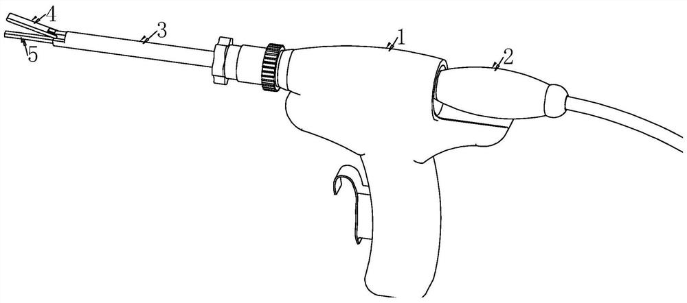
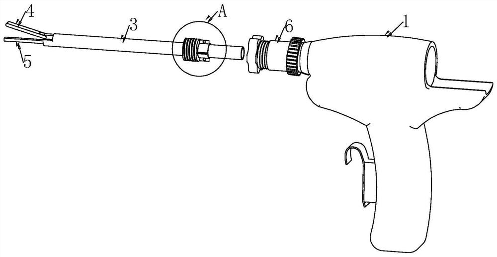
[0038] see Figure 1-7 , an ultrasonic knife with a new knife rod structure, including a handle 1, an ultrasonic transducer 2 is threaded on the right side of the handle 1 close to the top, and a fixed sleeve 6 is threaded on the left side of the handle 1 close to the top , fixed sleeve 6 inside is provided with knife bar 3, and the position of knife bar 3 outer wall close to the left end is rotatably connected with pincer head 4, and the position of knife bar 3 inner left end is movably inserted with knife bar head 5.

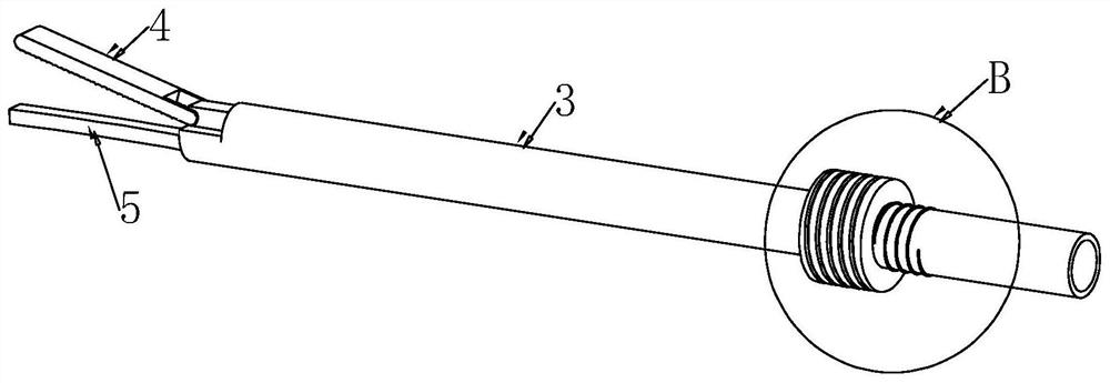
[0039] refer to Figure 4 , Figure 5 , the knife bar 3 is threadedly connected with a fixed ring 10 through the first thread 7, and the outer wall of the fixed ring 10 is fixedly connected with a first fixed plate 11 evenly distributed, and the middle position of the first fixed plate 11 is provided with a first fixed hole 12, and the knife bar 3 The position near the right end of the outer wall is provided with a first thread 7, and the outer wall of the c...


PUM


Abstract

The invention discloses an ultrasonic scalpel with a novel scalpel rod structure and a using method of the ultrasonic scalpel, and belongs to the field of ultrasonic scalpels. The ultrasonic scalpel comprises a grab handle; an ultrasonic transducer is in threaded connection with the position, close to the top, of the right side of the grab handle; a fixing sleeve is in threaded connection with theposition, close to the top, of the left side of the grab handle; a scalpel rod is arranged in the fixing sleeve; a clamp head is rotationally connected to the position, close to the left end, of theouter wall of the scalpel rod; a scalpel rod head is movably inserted into the left end of the scalpel rod; a first thread is arranged at the position, close to the right end, of the outer wall of thescalpel rod; a limiting stabilizing ring is fixedly connected to the position, close to the left side of the first thread, of the outer wall of the scalpel rod; and a first threaded groove is formedin the outer wall of the limiting stabilizing ring. According to the ultrasonic scalpel, when the scalpel rod is connected with the grab handle, force is not directly applied to the scalpel rod, so that the situation that due to the fact that the scalpel rod is relatively thin, the position of the joint is damaged, the scalpel rod is scrapped, and medical resources are wasted is avoided.

Description

technical field [0001] The invention relates to the field of ultrasonic scalpels, more specifically, to an ultrasonic scalpel with a novel cutter bar structure and a method for using the same. Background technique [0002] Ultrasonic scalpel uses ultrasonic energy to process soft tissue, cutting and coagulation are completed at the same time, and can ensure minimal lateral thermal damage to tissue. With the popularity of minimally invasive surgery, the ultrasonic scalpel has become a conventional surgical instrument. The ultrasonic scalpel is mainly composed of three parts: ultrasonic transducer, gun handle, and knife rod. The transducer converts the electric energy delivered by the host into ultrasonic resonance energy with a frequency of 55.5 kHz. The transducer is inserted into the tail end of the handle and connected with the cutter body in the cutter holder. The transducer transmits the ultrasonic vibration energy to the cutter head at the front end through the cutter ...

Claims


Application Information

Patent Timeline
IPC IPC(8): A61B17/32
CPCA61B17/320068
Inventor 张晓斌王成
Owner THE FIRST AFFILIATED HOSPITAL OF ANHUI MEDICAL UNIV
Why Eureka
Try Eureka